 |
 |
|
||||
|
By
Wikipedia, A fluid flowing past the surface of a body exerts a force on it. Lift is defined to be the component of this force which is perpendicular to the oncoming flow direction. It contrasts with the drag force, which is defined to be the component of the fluid-dynamic force parallel to the flow direction. If the fluid is air, the force is called an aerodynamic force. An airfoil is a streamlined shape that is capable of generating significantly more lift than drag. Aerodynamic lift is commonly associated with the wing of a fixed-wing aircraft, although lift is also generated by propellers; helicopter rotors; rudders, sails and keels on sailboats; hydrofoils; wings on auto racing cars; wind turbines and other streamlined objects. While common meanings of the word "lift" suggest that lift opposes gravity, lift can be in any direction. When an aircraft is flying straight and level (cruise) most of the lift opposes gravity. However, when an aircraft is climbing, descending, or banking in a turn, for example, the lift is tilted with respect to the vertical and the lift is greater than, or less than, the weight of the aircraft. Lift may also be entirely downwards in some aerobatic manoeuvres, or on the wing on a racing car. In this last case, the term downforce is often used. Non-streamlined objects such as bluff bodies and plates (not parallel to the flow) may also generate lift when moving relative to the fluid. This lift may be steady, or it may oscillate due to vortex shedding. Interaction of the object's flexibility with the vortex shedding may enhance the effects of fluctuating lift and cause vortex-induced vibrations. Description of lift on an airfoilLift is generated in accordance with the fundamental principles of physics. The most relevant physics reduce to three principles:
In the last principle, the pressure depends on the other flow properties, such as its mass density, through the (thermodynamic) equation of state, while the shear stresses are related to the flow through the air's viscosity. Application of the viscous shear stresses to Newton's second law for an airflow results in the Navier–Stokes equations. But in many instances approximations suffice for a good description of lifting airfoils: in large parts of the flow viscosity may be neglected. Such an inviscid flow can be described mathematically through the Euler equations, resulting from the Navier-Stokes equations when the viscosity is neglected. The Euler equations for a steady and inviscid flow can be integrated along a streamline, resulting in Bernoulli's equation. The particular form of Bernoulli's equation found depends on the equation of state used. At low Mach numbers, compressibility effects may be neglected, resulting in an incompressible flow approximation. In incompressible and inviscid flow the Bernoulli equation is just an integration of Newton's second law—in the form of the description of momentum evolution by the Euler equations—along a streamline. Explaining lift while considering all of the principles involved is a complex task and is not easily simplified. As a result, there are numerous different explanations of lift with different levels of rigour and complexity. For example, there is an explanation based directly on Newton’s laws of motion; and an explanation based on Bernoulli’s principle. Neither of these explanations is incorrect, but each appeals to a different audience. In order to explain lift as it applies to an airplane wing, consider the incompressible flow around a 2-D, symmetric airfoil at positive angle of attack in a uniform free stream. Instead of considering the case where an airfoil moves through a fluid as seen by a stationary observer, it is equivalent and simpler to consider the picture when the observer follows the airfoil and the fluid moves past it. The explanation presented first is a summary of the most scientifically complete and accepted explanation; alternative and generally more accessible explanations follow below. Lift in an established flow
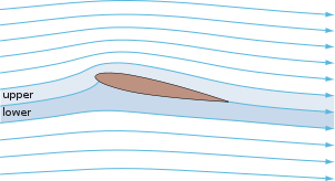
The image to the right shows the streamlines over a NACA 0012 airfoil computed using potential flow theory, a simplified model of the real flow. The flow approaching an airfoil can be divided into two streamtubes, which are defined based on the area between two streamlines. By definition, fluid never crosses a streamline in a steady flow; hence mass is conserved within each streamtube. One streamtube travels over the upper surface, while the other travels over the lower surface; dividing these two tubes is a dividing line (the stagnation streamline) that intersects the airfoil on the lower surface, typically near to the leading edge. The stagnation streamline leaves the airfoil at the sharp trailing edge, a feature of the flow known as the Kutta condition. In calculating the flow shown, the Kutta condition was imposed as an initial assumption; the justification for this assumption is explained below. The upper stream tube constricts as it flows up and around the airfoil, a part of the so-called upwash. From the conservation of mass, the flow speed must increase as the stream tube area decreases. The area of the lower stream tube increases, causing the flow inside the tube to slow down. It is typically the case that the air parcels traveling over the upper surface will reach the trailing edge before those traveling over the bottom. From Bernoulli's principle, the pressure on the upper surface where the flow is moving faster is lower than the pressure on the lower surface. The pressure difference thus creates a net aerodynamic force, pointing upward and downstream to the flow direction. The component of the force normal to the free stream is considered to be lift; the component parallel to the free stream is drag. In conjunction with this force by the air on the airfoil, by Newton's third law, the airfoil imparts an equal-and-opposite force on the surrounding air that creates the downwash. Measuring the momentum transferred to the downwash is another way to determine the amount of lift on the airfoil. Flowfield formationIn attempting to explain why the flow follows the upper surface of the airfoil, the situation gets considerably more complex. It is here that many simplifications are made in presenting lift to various audiences, some of which are explained after this section. Consider the case of an airfoil accelerating from rest in a viscous flow. Lift depends entirely on the nature of viscous flow past certain bodies: in inviscid flow (i.e. assuming that viscous forces are negligible in comparison to inertial forces), there is no lift without imposing a net circulation, the proper amount of which can be determined by applying the Kutta condition. In a viscous flow like in the physical world, however, the lift and other properties arise naturally as described here. When there is no flow, there is no lift and the forces acting on the airfoil are zero. At the instant when the flow is “turned on”, the flow is undeflected downstream of the airfoil and there are two stagnation points on the airfoil (where the flow velocity is zero): one near the leading edge on the bottom surface, and another on the upper surface near the trailing edge. The dividing line between the upper and lower streamtubes mentioned above intersects the body at the stagnation points. Since the flow speed is zero at these points, by Bernoulli's principle the static pressure at these points is at a maximum. As long as the second stagnation point is at its initial location on the upper surface of the wing, the circulation around the airfoil is zero and, in accordance with the Kutta–Joukowski theorem, there is no lift. The net pressure difference between the upper and lower surfaces is zero. The effects of viscosity are contained within a thin layer of fluid called the boundary layer, close to the body. As flow over the airfoil commences, the flow along the lower surface turns at the sharp trailing edge and flows along the upper surface towards the upper stagnation point. The flow in the vicinity of the sharp trailing edge is very fast and the resulting viscous forces cause the boundary layer to accumulate into a vortex on the upper side of the airfoil between the trailing edge and the upper stagnation point. This is called the starting vortex. The starting vortex and the bound vortex around the surface of the wing are two halves of a closed loop. As the starting vortex increases in strength the bound vortex also strengthens, causing the flow over the upper surface of the airfoil to accelerate and drive the upper stagnation point towards the sharp trailing edge. As this happens, the starting vortex is shed into the wake,and is a necessary condition to produce lift on an airfoil. If the flow were stopped, there would be a corresponding "stopping vortex". Despite being an idealization of the real world, the “vortex system” set up around a wing is both real and observable; the trailing vortex sheet most noticeably rolls up into wing-tip vortices. The upper stagnation point continues moving downstream until it is coincident with the sharp trailing edge (as stated by the Kutta condition). The flow downstream of the airfoil is deflected downward from the free-stream direction and, from the reasoning above in the basic explanation, there is now a net pressure difference between the upper and lower surfaces and an aerodynamic force is generated. Alternative explanations for the generation of lift
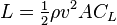
Many alternative explanations for the generation of lift by an airfoil have been put forward, of which a few are presented here. Most of them are intended to explain the phenomenon of lift to a general audience. Although the explanations may share features in common with the explanation above, additional assumptions and simplifications may be introduced. This reduces the validity of an alternative explanation to a limited sub-class of lift generating conditions, or does not allow a quantitative analysis. Several theories introduce assumptions which proved to be wrong, like the equal transit-time theory. Equal transit-timeAn explanation of lift frequently encountered in basic or popular sources is the equal transit-time theory. Equal transit-time states that because of the longer path of the upper surface of an airfoil, the air going over the top must go faster in order to catch up with the air flowing around the bottom. Such that the parcels of air that are divided at the leading edge, and travel above and below an airfoil must rejoin when they reach the trailing edge. However, this is not accurate and the fact that this is not generally the case can be readily observed. Although it is true that the air moving over the top of a wing generating lift does move faster, there is no requirement for equal transit time. In fact the air moving over the top of an airfoil generating lift is always moving much faster than the equal transit theory would imply. Coandă effectIn a limited sense, the Coandă effect refers to the tendency of a fluid jet to stay attached to an adjacent surface that curves away from the flow, and the resultant entrainment of ambient air into the flow. The effect is named for Henri Coandă, the Romanian aerodynamicist who exploited it in many of his patents. One of the first known uses was in his patent for a high-lift device that used a fan of gas exiting at high speed from an internal compressor. This circular spray was directed radially over the top of a curved surface shaped like a lens to decrease the pressure on that surface. The total lift for the device was caused by the difference between this pressure and that on the bottom of the craft. Two aircraft, the Antonov An-72 and An-74 "Coaler", use the exhaust from top-mounted jet engines flowing over the wing to enhance lift, as do the Boeing YC-14 and the McDonnell Douglas YC-15.The effect is also used in high-lift devices such as a blown flap. More broadly, some consider the effect to include the tendency of any fluid boundary layer to adhere to a curved surface, not just the boundary layer accompanying a fluid jet. It is in this broader sense that the Coandă effect is used by some to explain lift. Jef Raskin, for example, describes a simple demonstration, using a straw to blow over the upper surface of a wing. The wing deflects upwards, thus supposedly demonstrating that the Coandă effect creates lift. This demonstration correctly demonstrates the Coandă effect as a fluid jet (the exhaust from a straw) adhering to a curved surface (the wing). However, the upper surface in this flow is a complicated, vortex-laden mixing layer, while on the lower surface the flow is quiescent. The physics of this demonstration are very different from that of the general flow over the wing. The usage in this sense is encountered in some popular references on aerodynamics. In the aerodynamics field, the Coandă effect is commonly defined in the more limited sense above and viscosity is used to explain why the boundary layer attaches to the surface of a wing. In terms of a difference in areasWhen a fluid flows relative to a solid body, the body obstructs the flow, causing some of the fluid to change its speed and direction in order to flow around the body. The obstructive nature of the solid body causes the streamlines to move closer together in some places, and further apart in others. When fluid flows past a 2-D cambered airfoil at zero angle of attack, the upper surface has a greater area (that is, the interior area of the airfoil above the chordline) than the lower surface and hence presents a greater obstruction to the fluid than the lower surface. This asymmetry causes the streamlines in the fluid flowing over the upper surface to move closer together than the streamlines over the lower surface. As a consequence of mass conservation, the reduced area between the streamlines over the upper surface results in a higher velocity than that over the lower surface. The upper streamtube is squashed the most in the nose region ahead of the maximum thickness of the airfoil, causing the maximum velocity to occur ahead of the maximum thickness. In accordance with Bernoulli's principle, where the fluid is moving faster the pressure is lower, and where the fluid is moving slower the pressure is greater. The fluid is moving faster over the upper surface, particularly near the leading edge, than over the lower surface so the pressure on the upper surface is lower than the pressure on the lower surface. The difference in pressure between the upper and lower surfaces results in lift. Newton's laws: Lift and the deflection of the flowThe direct relationship between the lift force and the downward deflection of the air by the wing helps to obtain an insight into the phenomenon of lift. This explanation relies on the second and third of Newton's laws of motion: The net force on an object is equal to its rate of momentum change and To every action there is an equal and opposite reaction.For a fluid, the momentum density is equal to mass density multiplied by the flow velocity. Now consider an airfoil in straight flight at constant speed, and observe the airflow from the frame of reference in which the velocity of the airfoil is zero. John D. Anderson explains the relationship between lift and downwash as follows: "The wing deflects the airflow such that the mean velocity vector behind the wing is canted slightly downward (…). Hence, the wing imparts a downward component of momentum to the air; that is, the wing exerts a force on the air, pushing the flow downward. From Newton's third law, the equal and opposite reaction produces a lift." This explanation of lift was used in the 1944 book Stick and Rudder by aviation writer Wolfgang Langewiesche: "… the wing keeps the airplane up by pushing the air down." Consequently, the lift is directly related to the deflection of the flow field behind the airfoil. One may be tempted to think that lift can be explained along this line of reasoning, saying that lift on the airfoil is caused by the downward deflection of the airflow. However, this is a misinterpretation of Newton's laws. One can just as well argue that the downwash behind the airfoil is an effect of the lift force: according to Newton's third law the upward lift is accompanied by a downward force on the air. This latter force is pushing the air down, which results in a downward deflection of the velocity vectors behind the airfoil. Newton's laws of motion are not sufficient to explain lift. Also a force model is needed. To see this, consider for example an object under the influence of gravity: Newton's law of gravity is required in addition to his laws of motion, in order to be able to describe the object's motion. So also for air flows a force model is needed, relating flow properties to resulting stresses. Primarily, in the case of aerodynamics, this is an equation of state describing the air pressure dependence on the other flow characteristics. In case of the flow around an airfoil at low Mach numbers, the usual force model results from the incompressible flow approximation. Then the mass density is constant and the pressure is such that it constraints the flow to be isochoric — air parcels are of constant volume as they move along with the flow. Methods to determine lift on an airfoilLift coefficientIf the lift coefficient for a wing at a specified angle of attack is known (or estimated using a method such as thin-airfoil theory), then the lift produced for specific flow conditions can be determined using the following equation: where
Kutta–Joukowski theoremLift can be calculated using potential flow theory by imposing a circulation. It is often used by practicing aerodynamicists as a convenient quantity in calculations, for example thin-airfoil theory and lifting-line theory. The circulation Γ is the line integral of the velocity of the air, in a closed loop around the boundary of an airfoil. It can be understood as the total amount of "spinning" (or vorticity) of air around the airfoil. The section lift/span L' can be calculated using the Kutta–Joukowski theorem: where ρ is the air density, V is the free-stream airspeed. Kelvin's circulation theorem states that circulation is conserved. There is conservation of the air's angular momentum. When an aircraft is at rest, there is no circulation. The challenge when using the Kutta–Joukowski theorem to determine lift is to determine the appropriate circulation for a particular airfoil. In practice, this is done by applying the Kutta condition, which uniquely prescribes the circulation for a given geometry and free-stream velocity. A physical understanding of the theorem can be observed in the Magnus effect, which is a lift force generated by a spinning cylinder in a free stream. Here the necessary circulation is induced by the mechanical rotation acting on the boundary layer, causing it to induce a faster flow around one side of the cylinder and a slower flow around the other. The asymmetric distribution of airspeed around the cylinder then produces a circulation in the outer inviscid flow. Pressure integrationThe force on the wing can be examined in terms of the pressure differences above and below the wing, which can be related to velocity changes by Bernoulli's principle. The total lift force is the integral of vertical pressure forces over the entire wetted surface area of the wing: where:
The above lift equation neglects the skin friction forces, which typically have a negligible contribution to the lift compared to the pressure forces. By using the streamwise vector i parallel to the freestream in place of k in the integral, we obtain an expression for the pressure drag Dp (which includes induced drag in a 3D wing). If we use the spanwise vector j, we obtain the side force Y. One method for calculating the pressure is Bernoulli's equation, which is the mathematical expression of Bernoulli's principle. This method ignores the effects of viscosity, which can be important in the boundary layer and to predict friction drag, which is the other component of the total drag in addition to Dp. The Bernoulli principle states that the sum total of energy within a parcel of fluid remains constant as long as no energy is added or removed. It is a statement of the principle of the conservation of energy applied to flowing fluids. A substantial simplification of this proposes that as other forms of energy changes are inconsequential during the flow of air around a wing and that energy transfer in/out of the air is not significant, then the sum of pressure energy and speed energy for any particular parcel of air must be constant. Consequently, an increase in speed must be accompanied by a decrease in pressure and vice-versa. It should be noted that this is not a causational relationship. Rather, it is a coincidental relationship, whatever causes one must also cause the other as energy can neither be created nor destroyed. It is named for the Dutch-Swiss mathematician and scientist Daniel Bernoulli, though it was previously understood by Leonhard Euler and others. Bernoulli's principle provides an explanation of pressure difference in the absence of air density and temperature variation (a common approximation for low-speed aircraft). If the air density and temperature are the same above and below a wing, a naive application of the ideal gas law requires that the pressure also be the same. Bernoulli's principle, by including air velocity, explains this pressure difference. The principle does not, however, specify the air velocity. This must come from another source, e.g., experimental data. In order to solve for the velocity of inviscid flow around a wing, the Kutta condition must be applied to simulate the effects of inertia and viscosity. The Kutta condition allows for the correct choice among an infinite number of flow solutions that otherwise obey the laws of conservation of mass and conservation of momentum. Lift forces on bluff bodiesThe flow around bluff bodies may also generate lift, besides a strong drag force. For instance, the flow around a circular cylinder generates a Kármán vortex street: vortices being shed in an alternating fashion from each side of the cylinder. The oscillatory nature of the flow is reflected in the fluctuating lift force on the cylinder, whereas the mean lift force is negligible. The lift force frequency is characterised by the dimensionless Strouhal number, which depends (among others) on the Reynolds number of the flow. For a flexible structure, this oscillatory lift force may induce vortex-induced vibrations. Under certain conditions — for instance resonance or strong spanwise correlation of the lift force — the resulting motion of the structure due to the lift fluctuations may be strongly enhanced. Such vibrations may pose problems, even collapse, in man-made tall structures like for instance industrial chimneys, if not properly taken care of in the design.
Text from Wikipedia is available under the Creative Commons Attribution/Share-Alike License; additional terms may apply.
Published in July 2009. Click here to read more articles related to aviation and space!
|

 |
|
Copyright 2004-2026 © by Airports-Worldwide.com, Vyshenskoho st. 36, Lviv 79010, Ukraine Legal Disclaimer |


![\begin{align}D_p &= \oint p\mathbf{n} \cdot\mathbf{i} \; \mathrm{d}A,\\[1.2ex]Y&= \oint p\mathbf{n} \cdot\mathbf{j} \; \mathrm{d}A.
\end{align}](http://upload.wikimedia.org/math/8/a/3/8a32dbbacc67e5d4dce3083011da2cde.png)