 |
 |
|
||||
|
By
Wikipedia,
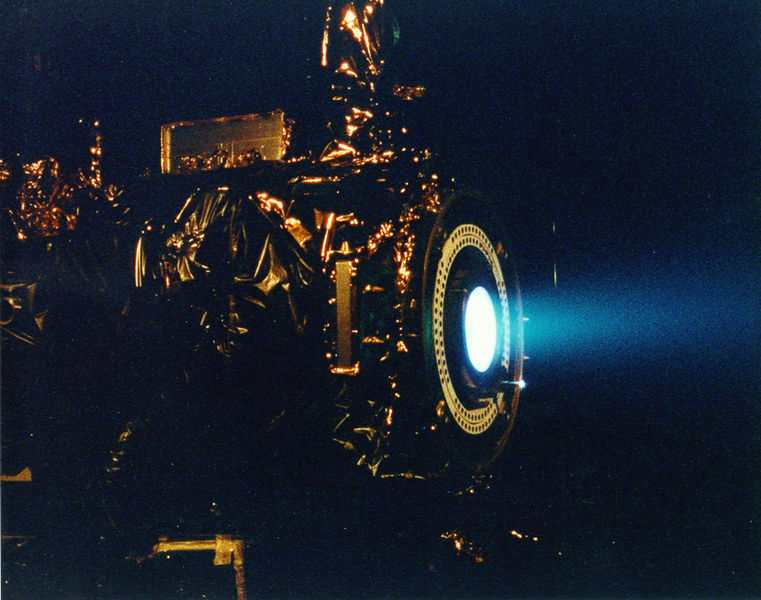
An ion thruster is a form of electric propulsion used for spacecraft propulsion that creates thrust by accelerating ions. Ion thrusters are categorized by how they accelerate the ions, using either electrostatic or electromagnetic force. Electrostatic ion thrusters use the Coulomb force and accelerate the ions in the direction of the electric field. Electromagnetic ion thrusters use the Lorentz force to accelerate the ions. Note that the term "ion thruster" frequently denotes the electrostatic or gridded ion thrusters, only. The thrust created in ion thrusters is very small compared to conventional chemical rockets, but a very high specific impulse, or propellant efficiency, is obtained. This high propellant efficiency is achieved through the very frugal propellant consumption of the ion thruster propulsion system. Due to their relatively high power needs, given the specific power of power supplies, and the requirement of an environment void of other ionized particles, ion thrust propulsion is currently practical only in outer space. OriginsDr. Robert H. Goddard, an American Rocket Pioneer first theorized on the subject in 1906.The first experiments with ion thrusters were carried out by Robert Goddard at Clark University from 1916-1917. The technique was recommended for near-vacuum conditions at high altitude, but thrust was demonstrated with ionized air streams at atmospheric pressure. The idea appeared again in Hermann Oberth's "Wege zur Raumschiffahrt” (Ways to Spaceflight), published in 1923, where he explained his thoughts on the mass savings of electric propulsion, predicted its use in spacecraft propulsion and attitude control, and advocated electrostatic acceleration of charged gases. A working ion thruster was built by Harold R. Kaufman in 1959 at the NASA Glenn facilities. It was similar to the general design of a gridded electrostatic ion thruster with mercury as its fuel. Suborbital tests of the engine followed during the 1960s and in 1964 the engine was sent into a suborbital flight aboard the Space Electric Rocket Test 1 (SERT 1). It successfully operated for the planned 31 minutes before falling back to Earth.
The Hall effect thruster was studied independently in the U.S. and the USSR in the 1950s and 60s. However, the concept of a Hall thruster was only developed into an efficient propulsion device in the former Soviet Union, whereas in the U.S., scientists focused instead on developing gridded ion thrusters. Hall effect thrusters were operated on Soviet satellites since 1972. Until the 1990s they were mainly used for satellite stabilization in North-South and in East-West directions. Some 100-200 engines completed their mission on Soviet and Russian satellites until the late 1990s. Soviet thruster design was introduced to the West in 1992 after a team of electric propulsion specialists, under the support of the Ballistic Missile Defense Organization, visited Soviet laboratories. General DescriptionIon thrusters utilize beams of ions (electrically charged atoms or molecules) to create thrust in accordance with Newton's third law. The method of accelerating the ions varies, but all designs take advantage of the charge/mass ratio of the ions. This ratio means that relatively small potential differences can create very high exhaust velocities. This reduces the amount of reaction mass or fuel required, but increases the amount of specific power required compared to chemical rockets. Ion thrusters are therefore able to achieve extremely high specific impulses. The drawback of the low thrust is low spacecraft acceleration because the mass of current electric power units is directly correlated with the amount of power given. This low thrust makes ion thrusters unsuited for launching spacecraft into orbit, but they are ideal for in-space propulsion applications. Various ion thrusters have been designed and they all generally fit under two categories. The thrusters are categorized as either electrostatic or electromagnetic. The main difference is how the ions are accelerated.
Electrostatic Ion ThrustersGridded electrostatic ion thrusters
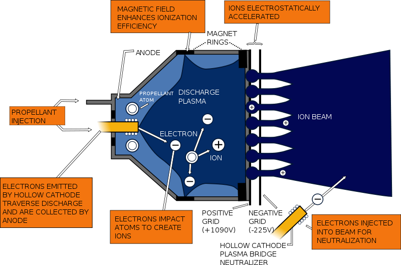
Gridded electrostatic ion thrusters commonly utilize xenon gas. This gas has no charge and is ionized by bombarding it with energetic electrons. These electrons can be provided from a hot cathode filament and accelerated in the electrical field of the cathode fall to the anode (Kaufman type ion thruster). Alternatively, the electrons can be accelerated by the oscillating electric field induced by an alternating magnetic field of a coil, which results in a self-sustaining discharge and omits any cathode (radiofrequency ion thruster). The positively charged ions are extracted by an extraction system consisting of 2 or 3 multi-aperture grids. After entering the grid system via the plasma sheath the ions are accelerated due to the potential difference between the first and second grid (named screen and accelerator grid) to the final ion energy of typically 1-2 keV, thereby generating the thrust. Ion thrusters emit a beam of positive charged xenon ions only. In order to avoid the charging-up of the spacecraft another cathode, placed near the engine, emits additional electrons (basically the electron current is the same as the ion current) into the ion beam. This also prevents the beam of ions from returning to the spacecraft and thereby cancelling the thrust. Gridded electrostatic ion thruster research (past/present):
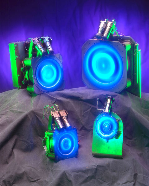
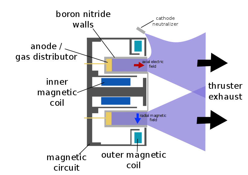
Hall effect thrustersHall effect thrusters accelerate ions with the use of an electric potential maintained between a cylindrical anode and a negatively charged plasma which forms the cathode. The bulk of the propellant (typically xenon or bismuth gas) is introduced near the anode, where it becomes ionized, and the ions are attracted towards the cathode, they accelerate towards and through it, picking up electrons as they leave to neutralize the beam and leave the thruster at high velocity. The anode is at one end of a cylindrical tube, and in the center is a spike which is wound to produce a radial magnetic field between it and the surrounding tube. The ions are largely unaffected by the magnetic field, since they are too massive. However, the electrons produced near the end of the spike to create the cathode are far more affected and are trapped by the magnetic field, and held in place by their attraction to the anode. Some of the electrons spiral down towards the anode, circulating around the spike in a Hall current. When they reach the anode they impact the uncharged propellant and cause it to be ionized, before finally reaching the anode and closing the circuit. Field Emission Electric Propulsion (FEEP)Field Emission Electric Propulsion (FEEP) thrusters use a very simple system of accelerating liquid metal ions to create thrust. Most designs use either caesium or indium as the propellant. The design consists of a small propellant reservoir that stores the liquid metal, a very small slit that the liquid flows through, and then the accelerator ring. Caesium and indium are used due to their high atomic weights, low ionization potentials, and low melting points. Once the liquid metal reaches the inside of the slit in the emitter, an electric field applied between the emitter and the accelerator ring causes the liquid metal to become unstable and ionize. This creates a positive ion, which can then be accelerated in the electric field created by the emitter and the accelerator ring. These positively charged ions are then neutralized by an external source of electrons in order to prevent charging of the spacecraft hull. Electromagnetic ThrustersPulsed Inductive Thrusters (PIT)Pulsed Inductive Thrusters (PIT) use pulses of thrust instead of one continuous thrust, and have the ability to run on power levels in the order of Megawatts (MW). PITs consist of a large coil encircling a cone shaped tube that emits the propellant gas as shown in the diagram. Ammonia is the gas commonly used in PIT engines. For each pulse of thrust the PIT gives, a large charge first builds up in a group of capacitors behind the coil and is then released. This creates a current that moves circularly in the direction of jθ as seen in the diagram. The current then creates a magnetic field in the outward radial direction (Br), which then creates a current in the ammonia gas that has just been released in the opposite direction of the original current. This opposite current ionizes the ammonia and these positively charged ions are accelerated away from the PIT engine due to the electric field jθ crossing with the magnetic field Br, which is due to the Lorentz Force. Magnetoplasmadynamic (MPD) / Lithium Lorentz Force Accelerator (LiLFA)Magnetoplasmadynamic (MPD) thrusters and Lithium Lorentz Force Accelerator (LiLFA) thrusters use roughly the same idea with the LiLFA thruster building off of the MPD thruster. Hydrogen, argon, ammonia, and nitrogen gas can be used as propellant. The gas first enters the main chamber where it is ionized into plasma by the electric field between the anode and the cathode. This plasma then conducts electricity between the anode and the cathode. This new current creates a magnetic field around the cathode which crosses with the electric field, thereby accelerating the plasma due to the Lorentz Force. The LiLFA thruster uses the same general idea as the MPD thruster, except for two main differences. The first difference is that the LiLFA uses lithium vapor, which has the advantage of being able to be stored as a solid. The other difference is that the cathode is replaced by multiple smaller cathode rods packed into a hollow cathode tube. The cathode in the MPD thruster is easily corroded due to constant contact with the plasma. In the LiLFA thruster the lithium vapor is injected into the hollow cathode and is not ionized to its plasma form/corrode the cathode rods until it exits the tube. The plasma is then accelerated using the same Lorentz Force. Electrodeless Plasma ThrustersElectrodeless Plasma Thrusters have two unique features, the removal of the anode and cathode electrodes and the ability to throttle the engine. The removal of the electrodes takes away the factor of erosion which limits lifetime on other ion engines. Neutral gas is first ionized by electromagnetic waves and then transferred to another chamber where it is accelerated by an oscillating electric and magnetic field, also known as the ponderomotive force. This separation of the ionization and acceleration stage give the engine the ability to throttle the speed of propellant flow, which then changes the thrust magnitude and specific impulse values. Electrothermal ThrustersElectrothermal thrusters use electric power to accelerate propellant. There are several types: Helicon Double Layer ThrusterA Helicon Double Layer thruster is a type of plasma thruster, which ejects high velocity ionized gas to provide thrust to a spacecraft. In this thruster design, gas is injected into a tubular chamber (the source tube) with one open end. Radio frequency AC power (at 13.56 MHz in the prototype design) is coupled into a specially shaped antenna wrapped around the chamber. The electromagnetic wave emitted by the antenna causes the gas to break down and form a plasma. The antenna then excites a Helicon wave in the plasma, which further heats the plasma. The device has a roughly constant magnetic field in the source tube (supplied by Solenoids in the prototype), but the magnetic field diverges and rapidly decreases in magnitude away from the source region, and might be thought of as a kind of magnetic nozzle. In operation, there is a sharp boundary between the high density plasma inside the source region, and the low density plasma in the exhaust, which is associated with a sharp change in electrical potential. The plasma properties change rapidly across this boundary, which is known as a current free electric double layer. The electrical potential is much higher inside the source region than in the exhaust, and this serves both to confine most of the electrons, and to accelerate the ions away from the source region. Enough electrons escape the source region to ensure that the plasma in the exhaust is neutral overall. ComparisonsThe following table compares actual test data of some ion thrusters:
The following thrusters are highly experimental and have been tested only in pulse mode.
LifetimeA major limiting factor of ion thrusters is their small thrust, which however is generated at a high propellant efficiency (mass utilisation, specific impulse). The efficiency comes from the high exhaust velocity, which in turn demands a lot of energy, and the performance is ultimately limited by the available spacecraft power. The low thrust requires ion thrusters to provide continuous thrust for a very long time in order to achieve the needed change in velocity (delta-v) for a particular mission. To achieve these delta-vs, ion thrusters are designed to last for periods of weeks to years. In practice the lifetime of ion thrusters is limited by several processes. In the electrostatic gridded ion thruster design, charge-exchange ions produced by the beam ions with the neutral gas flow can be accelerated towards the negatively biased accelerator grid and cause grid erosion. End-of-life is reached when either a structural failure of the grid occurs or the holes in the accelerator grid become so large that the ion extraction is largely affected (e.g. by the occurrence of electron backstreaming). Grid erosion cannot be avoided and is the major lifetime-limiting factor. By a thorough grid design and material selection, lifetimes of 20,000 hours and far beyond are reached, which is sufficient to fulfill current space missions. A test of the NASA Solar electric propulsion Technology Application Readiness (NSTAR) electrostatic ion thruster resulted in 30,472 hours (roughly 3.5 years) of continuous thrust at maximum power. The test was concluded prior to any failure and test results showed the engine was not approaching failure either. The Hall thrusters suffer from very strong erosion of the ceramic discharge chamber. Due to the rather high discharge voltages of up to 1000V energetic ions can impinge to the chamber walls and erode material. Lifetimes of a few thousand hours are reached. PropellantsIonisation energy represents a very large percentage of the energy needed to run ion drives. The ideal propellant for ion drives is thus a propellant molecule or atom with a high mass/ionisation energy ratio. In addition, the propellant should not cause erosion of the thruster to any great degree to permit long life; and should not contaminate the vehicle. Many current designs use xenon gas due to its low ionisation energy, reasonably high atomic number, inert nature, and low erosion. However, xenon is globally in short supply and very expensive. Older designs used mercury, but this is toxic and expensive, and tended to contaminate the vehicle with the metal. Other propellants such as bismuth show promise and are areas of research, particularly for gridless designs such as Hall effect thrusters. VASIMR design (and other plasma based engines) are theoretically able to use practically any material for propellant. However, in current tests the most practical propellant is Argon, which is a relatively abundant and cheap gas. ApplicationsIon thrusters have many applications for in-space propulsion. The best applications of the thrusters make use of the long lifetime when significant thrust is not needed. Examples of this include orbit transfers, attitude adjustments, drag compensation for low earth orbits, and ultra fine adjustments for more scientific missions. Ion thrusters can also be used for interplanetary and deep space missions where time is not crucial. Continuous thrust over a very long time can potentially build up a larger velocity than traditional chemical rockets. MissionsOf all the electric thrusters, ion thrusters have been the most seriously considered commercially and academically in the quest for interplanetary missions and orbit raising maneuvers. Ion thrusters are seen as the best solution for these missions as they require very high change in velocity overall that can be built up over long periods of time. Several spacecraft have operated with this technology. SERTThe first was SERT-1 which tested two mercury ion engines for thousands of running hours in the 1970s. Deep Space 1NASA has developed an ion thruster called NSTAR for use in their interplanetary missions. This thruster was tested in the highly successful space probe Deep Space 1, launched in 1998. Hughes has developed the XIPS (Xenon Ion Propulsion System) for performing stationkeeping on geosynchronous satellites. These are electrostatic ion thrusters that work by a principle different from that of the Hall effect thruster. ArtemisOn 12 July 2001, the European Space Agency failed to launch their Artemis telecommunication satellite to desired altitude, and left it in a decaying orbit. The satellite's chemical propellant supply was sufficient to transfer it to a semi-stable orbit, and over the next 18 months the experimental onboard ion propulsion system RIT-10 (intended for secondary stationkeeping and maneuvering) was utilized to transfer it to a geostationary orbit. HayabusaThe Japanese space agency's Hayabusa, which was launched in 2003 and successfully rendezvoused with the asteroid 25143 Itokawa and remained in close proximity for many months to collect samples and information, is powered by four xenon Ion Engines. It is using xenon ions generated by microwave ECR, and a Carbon / Carbon-composite material for acceleration grid which is resistant to erosion. Smart 1The Hall effect thruster is a type of ion thruster that has been used for decades for station keeping by the Soviet Union and is now also applied in the West: the European Space Agency's satellite Smart 1, launched in 2003, used it (Snecma PPS-1350-G). This satellite completed its mission on 3 September 2006, in a controlled collision on the Moon's surface, after a trajectory deviation to be able to see the 3 meter crater the impact created on the visible side of the moon. DawnDawn was launched on 27 September 2007 to explore the asteroid Vesta and the dwarf planet Ceres. To cruise from Earth to its targets it uses three Deep Space 1 heritage Xenon ion thrusters (firing only one at a time) to take it in a long outward spiral. An extended mission in which Dawn explores other asteroids after Ceres is also possible. Dawn's ion drive is capable of accelerating from 0 to 60 mph (97 km/h) in 4 days. GOCEESA's Gravity Field and Steady-State Ocean Circulation Explorer was launched on March 16, 2009. It will continue to use ion propulsion throughout its twenty month mission to combat the air-drag it experiences in its low orbit. LISA PathfinderLISA Pathfinder is an ESA spacecraft to be launched in 2010. It will not use ion thrusters as its primary propulsion system, but will use both colloid thrusters and FEEP for very precise altitude control—the low thrusts of these propulsion devices make it possible to move the spacecraft incremental distances very accurately. It is a test for the possible LISA mission. See also
Text from Wikipedia is available under the Creative Commons Attribution/Share-Alike License; additional terms may apply.
Published in July 2009. Click here to read more articles related to aviation and space!
|

 |
|
Copyright 2004-2026 © by Airports-Worldwide.com, Vyshenskoho st. 36, Lviv 79010, Ukraine Legal Disclaimer |