 |
 |
|
||||
|
By
Wikipedia,
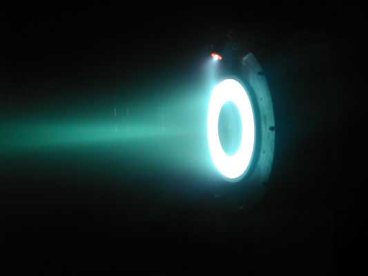
In spacecraft propulsion, a Hall thruster is a type of ion thruster in which the propellant is accelerated by an electric field. Hall thrusters trap electrons in a magnetic field and then use the electrons to ionize propellant, efficiently accelerate the ions to produce thrust, and neutralize the ions in the plume. Hall thrusters are sometimes referred to as Hall Effect Thrusters or Hall Current Thrusters. Hall thrusters are able to accelerate their exhaust to speeds of around 15–30 km/s, and can produce thrusts of about one newton. HistoryHall thrusters were studied independently in the US and the USSR in the 1950s and '60s. However, the concept of a Hall thruster was only developed into an efficient propulsion device in the former Soviet Union, whereas in the US, scientists focused instead on developing gridded ion thrusters. Two types of Hall thrusters were developed in the Soviet Union:
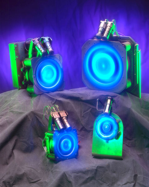
The common SPD design was largely the work of A. I. Morozov. SPD engines were operated since 1972. They were mainly used for satellite stabilization in North-South and in East-West directions. Since then until the late 1990s 118 SPD engines completed their mission and some 50 continued to be operated. Thrust of the first generation of SPD engines, SPD-50 and SPD-60 was 20 and 30 mN respectively. In 1982 SPD-70 and SPD-100 were introduced, their thrust being 40 mN and 83 mN. In the post-Soviet Russia high-power (a few kilowatts) SPD-140, SPD-160, SPD-180, T-160 and low-power (less than 500 W) SPD-35 were introduced. Soviet and Russian DAS-type engines include D-38 and D-55. Soviet-built thrusters were introduced to the West in 1992 after a team of electric propulsion specialists, under the support of the Ballistic Missile Defense Organization, visited Soviet laboratories and experimentally evaluated the SPD-100 (i.e., a 100 mm diameter SPT thruster). Over 200 Hall thrusters have been flown on Soviet/Russian satellites in the past thirty years. They were used mainly for stationkeeping and small orbital corrections. Currently Hall Thruster research, design, and theoretical modelling is led by experts at NASA Glenn Research Center and the Jet Propulsion Laboratory. A considerable amount of development is being conducted in industry, such as Aerojet and Busek Co. This technology was used on the European lunar mission SMART-1 and is used on a number of commercial geostationary satellites. OperationThe essential working principle of the Hall thruster is that it uses an electrostatic potential to accelerate ions up to high speeds. In a Hall thruster the attractive negative charge is provided by an electron plasma at the open end of the thruster instead of a grid. A radial magnetic field of a few milliteslas is used to hold the electrons in place, where the combination of the magnetic field and an attraction to the anode force a fast circulating electron current around the axis of the thruster and only a slow axial drift towards the anode occurs.
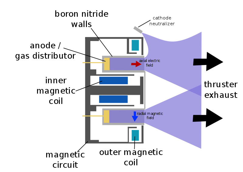
A schematic of a Hall thruster is shown in the image to the right. An electric potential on the order of 300 volts is applied between the anode and cathode. The central spike forms one pole of an electromagnet and is surrounded by an annular space and around that is the other pole of the electromagnet, with a radial magnetic field in-between. The propellant, such as xenon gas is fed through the anode, which has numerous small holes in it to act as a gas distributor. Xenon propellant is used because of its high molecular weight and low ionization potential. As the neutral xenon atoms diffuse into the channel of the thruster, they are ionized by collisions with high energy circulating electrons (10–20 eV or 100,000 to 250,000 °C). Once ionised the xenon ions typically have a charge of +1 though a small fraction (~10%) are +2. The xenon ions are then accelerated by the electric field between the anode and the cathode. The ions quickly reach speeds of around 15,000 m/s for a specific impulse of 1,500 seconds (15 kN·s/kg). Upon exiting however, the ions pull an equal number of electrons with them, creating a plume with no net charge. The axial magnetic field is designed to be strong enough to substantially deflect the low-mass electrons, but not the high-mass ions which have a much larger gyroradius and are hardly impeded. The majority of electrons are thus stuck orbiting in the region of high radial magnetic field near the thruster exit plane, trapped in E×B (axial electric field and radial magnetic field). This orbital rotation of the electrons is a circulating Hall current and it is from this that the Hall thruster gets its name. Collisions and instabilities allow some of the electrons to be freed from the magnetic field and they drift towards the anode. About 30% of the discharge current is an electron current which doesn't produce thrust, which limits the energetic efficiency of the thruster; the other 70% of the current is in the ions. Because the majority of electrons are trapped in the Hall current, they have a long residence time inside the thruster and are able to ionize almost all (~90%) of the xenon propellant. The ionization efficiency of the thruster is thus around 90%, while the discharge current efficiency is around 70% for a combined thruster efficiency of around 63% (= 90% × 70%). The magnetic field thus ensures that the discharge power predominately goes into accelerating the xenon propellant and not the electrons, and the thruster turns out to be reasonably efficient. Compared to chemical rockets the thrust is very small, on the order of 80 mN for a typical thruster. For comparison, the weight of a coin like the U.S. quarter or a 20-cent Euro coin is approximately 60 mN. However, Hall thrusters operate at the high specific impulses that is achieved with ion thrusters. One particular advantage of Hall thrusters, as compared to an ion thruster, is that the generation and acceleration of the ions takes place in a quasi-neutral plasma and so there is no Child-Langmuir charge (space charge) saturated current limitation on the thrust density, and thus thrust is high for electrically accelerated thrusters. Another advantage is that these thrusters can use a wider variety of propellants supplied to the anode, even oxygen, although something easily ionised is needed at the cathode. One propellant that is starting to be used is liquid bismuth due to its low cost, high mass and low partial pressure. ApplicationsThe solar electric propulsion system of the European Space Agency's SMART-1 spacecraft used a Hall thruster (Snecma PPS-1350-G). Over the course of 13 months and 289 engine pulses it had consumed about 58.8 kg of xenon and produced a delta-v of 2737 m/s (46.5 m/s per kg xenon). Current researchCurrent research on Hall thrusters is ongoing and focuses mainly on
A Hall thruster typically operates at around 50–60% thrust efficiency and provides specific impulse from 1,200 to 1,800 seconds (12 to 18 kN·s/kg), and thrust-to-power ratios of 50–70 mN/kW. See alsoExternal links
Text from Wikipedia is available under the Creative Commons Attribution/Share-Alike License; additional terms may apply.
Published in July 2009. Click here to read more articles related to aviation and space!
|

 |
|
Copyright 2004-2026 © by Airports-Worldwide.com, Vyshenskoho st. 36, Lviv 79010, Ukraine Legal Disclaimer |