 |
 |
|
||||
|
By
Wikipedia,
The Instrument Landing System (ILS) is a ground-based instrument approach system that provides precision guidance to an aircraft approaching and landing on a runway, using a combination of radio signals and, in many cases, high-intensity lighting arrays to enable a safe landing during instrument meteorological conditions (IMC), such as low ceilings or reduced visibility due to fog, rain, or blowing snow. Instrument Approach Procedure charts (or "approach plates") are published for each ILS approach, providing pilots with the needed information to fly an ILS approach during instrument flight rules (IFR) operations, including the radio frequencies used by the ILS components or navaids and the minimum visibility requirements prescribed for the specific approach. Radio-navigation aids must keep a certain degree of accuracy (given by international standards, FAA, ICAO...); to assure this is the case, Flight inspection organizations check periodically critical parameters with properly equipped aircraft to calibrate and certify ILS precision. Principle of operationAn ILS consists of two independent sub-systems, one providing lateral guidance (Localizer), the other vertical guidance (Glideslope or Glide Path) to aircraft approaching a runway. Aircraft guidance is provided by the ILS receivers in the aircraft by performing a modulation depth comparison.
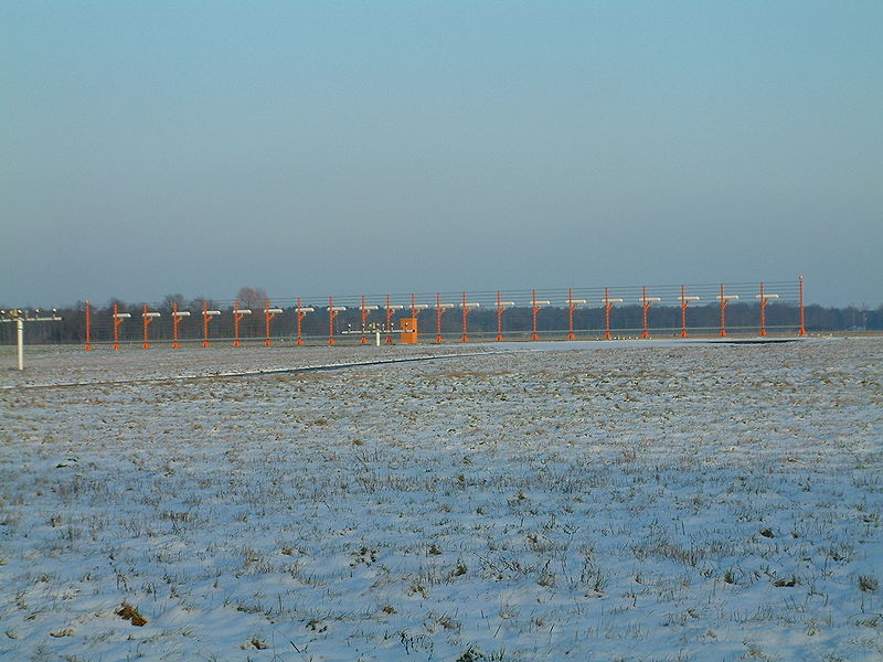
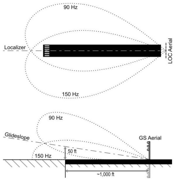
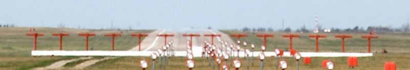
A localizer (LOC, or LLZ in Europe) antenna array is normally located beyond the departure end of the runway and generally consists of several pairs of directional antennas. Two signals are transmitted on one out of 40 ILS channels between the carrier frequency range 108.10 MHz and 111.95 MHz (but only the odd kHz, so 108.10 108.15 108.30 and so on are LOC frequencies but 108.20 108.25 108.40 and so on are not). One is modulated at 90 Hz, the other at 150 Hz and these are transmitted from separate but co-located antennas. Each antenna transmits a narrow beam, one slightly to the left of the runway centerline, the other to the right. The localizer receiver on the aircraft measures the Difference in the Depth of Modulation (DDM) of the 90 Hz and 150 Hz signals. For the localizer, the depth of modulation for each of the modulating frequencies is 20 percent. The difference between the two signals varies depending on the position of the approaching aircraft from the centerline. If there is a predominance of either 90 Hz or 150 Hz modulation, the aircraft is off the centerline. In the cockpit, the needle on the Horizontal Situation Indicator, or HSI (The Instrument part of the ILS), or CDI (Course deviation indicator), will show that the aircraft needs to fly left or right to correct the error to fly down the center of the runway. If the DDM is zero the aircraft is on the centerline of the localizer coinciding with the physical runway centerline. A glideslope or Glidepath (GP) antenna array is sited to one side of the runway touchdown zone. The GP signal is transmitted on a carrier frequency between 329.15 and 335 MHz using a technique similar to that of the localizer. The centerline of the glideslope signal is arranged to define a glideslope of approximately 3° above horizontal (ground level). The beam is 1.4° deep; 0.7° below the glideslope centerline and 0.7° above the glideslope centerline. Localizer and glideslope carrier frequencies are paired so that only one selection is required to tune both receivers. These signals are displayed on an indicator in the instrument panel. This instrument is generally called the omni-bearing indicator or nav indicator. The pilot controls the aircraft so that the indications on the instrument (i.e. the course deviation indicator) remain centered on the display. This ensures the aircraft is following the ILS centreline (i.e. it provides lateral guidance). Vertical guidance, shown on the instrument by the glideslope indicator, aids the pilot in reaching the runway at the proper touchdown point. Some aircraft possess the ability to route signals into the autopilot, allowing the approach to be flown automatically by the autopilot. Localizer
In addition to the previously mentioned navigational signals, the localizer provides for ILS facility identification by periodically transmitting a 1020 Hz morse code identification signal. For example, the ILS for runway 04R at John F. Kennedy International Airport transmits IJFK to identify itself, while runway 04L is known as IHIQ. This lets users know the facility is operating normally and that they are tuned to the correct ILS. The glideslope transmits no identification signal, so ILS equipment relies on the localizer for identification. Modern localizer antennas are highly directional. However, usage of older, less directional antennas allows a runway to have a non-precision approach called a localizer back course. This lets aircraft land using the signal transmitted from the back of the localizer array. This signal is reverse sensing so a pilot may have to fly opposite the needle indication (depending on the equipment installed in the aircraft). Highly directional antennas do not provide a sufficient signal to support a backcourse. In the United States, backcourse approaches are commonly associated with Category I systems at smaller airports that do not have an ILS on both ends of the primary runway. Marker beacons
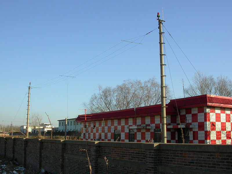
On most installations marker beacons operating at a carrier frequency of 75 MHz are provided. When the transmission from a marker beacon is received it activates an indicator on the pilot's instrument panel and the tone of the beacon is audible to the pilot. The distance from the runway at which this indication should be received is promulgated in the documentation for that approach, together with the height at which the aircraft should be if correctly established on the ILS. This provides a check on the correct function of the glideslope. In modern ILS installations a DME is installed, co-located with the ILS, to augment or replace marker beacons. A DME continuously displays the aircraft's distance to the runway. Outer marker
The outer marker should be located 7.2 km (3.9 NM) from the threshold except that, where this distance is not practicable, the outer marker may be located between 6.5 and 11.1 km (3.5 and 6 NM) from the threshold. The modulation is repeated Morse-style dashes of a 400 Hz tone. The cockpit indicator is a blue lamp that flashes in unison with the received audio code. The purpose of this beacon is to provide height, distance and equipment functioning checks to aircraft on intermediate and final approach. In the United States, an NDB is often combined with the outer marker beacon in the ILS approach (called a Locator Outer Marker, or LOM); in Canada, low-powered NDBs have replaced marker beacons entirely. Middle markerThe middle marker should be located so as to indicate, in low visibility conditions, the missed approach point, and the point that visual contact with the runway is imminent, ideally at a distance of approximately 3,500 ft (1,100 m) from the threshold. It is modulated with a 1300 Hz tone as alternating dots and dashes at the rate of two per second. The cockpit indicator is an amber lamp that flashes in unison with the received audio code. Inner markerThe inner marker, when installed, shall be located so as to indicate in low visibility conditions the imminence of arrival at the runway threshold. This is typically the position of an aircraft on the ILS as it reaches Category II minima. Ideally at a distance of approximately 1,000 ft (300 m) from the threshold. The modulation is Morse-style dots at 3000 Hz. The cockpit indicator is a white lamp that flashes in unison with the received audio code. DMEDistance measuring equipment (DME) provides pilots with a slant range measurement of distance to the runway in nautical miles. DMEs are augmenting or replacing markers in many installations. The DME provides more accurate and continuous monitoring of correct progress on the ILS glideslope to the pilot, and does not require an installation outside the airport boundary. When used in conjunction with an ILS, the DME is often sited midway between the reciprocal runway thresholds with the internal delay modified so that one unit can provide distance information to either runway threshold. On approaches where a DME is specified in lieu of marker beacons, the aircraft must have at least one operating DME unit to begin the approach, and a "DME Required" restriction will be noted on the Instrument Approach Procedure. MonitoringIt is essential that any failure of the ILS to provide safe guidance be detected immediately by the pilot. To achieve this, monitors continually assess the vital characteristics of the transmissions. If any significant deviation beyond strict limits is detected, either the ILS is automatically switched off or the navigation and identification components are removed from the carrier. Either of these actions will activate an indication ('failure flag') on the instruments of an aircraft using the ILS. Approach lightingSome installations include medium or high intensity approach light systems. Most often, these are at larger airports. The approach lighting system (abbreviated ALS) assists the pilot in transitioning from instrument to visual flight, and to align the aircraft visually with the runway centerline. At many non-towered airports, the intensity of the lighting system can be adjusted by the pilot, for example the pilot can click their microphone 7 times to turn on the lights, then 5 times to turn them to medium intensity. Use of the Instrument Landing SystemAt controlled airports, air traffic control will direct aircraft to the localizer via assigned headings, making sure aircraft do not get too close to each other (maintain separation), but also avoiding delay as much as possible. Several aircraft can be on the ILS at the same time, several miles apart. An aircraft that has come within two and a half degrees of the localizer course (half scale deflection shown by the course deviation indicator) is said to be established on the approach. Typically, an aircraft will be established by at least two miles prior to the final approach fix (glideslope intercept at the specified altitude). Aircraft deviation from the optimal path is indicated to the flight crew by means of display with "needles" (a carry over from when an analog meter movement would indicate deviation from the course line via voltages sent from the ILS receiver). The output from the ILS receiver goes both to the display system (Head Down Display and Head-Up Display if installed) and can also go to the Flight Control Computer. An aircraft landing procedure can be either "coupled", where the Flight Control Computer directly flies the aircraft and the flight crew monitor the operation; or "uncoupled" (manual) where the flight crew fly the aircraft uses the HUD and manually control the aircraft to minimize the deviation from flight path to the runway centreline. Rate-of-descent formulaA useful formula pilots use to calculate the descent rate on the glideslope.
where:
If the glideslope is the standard 3 degrees then the formula can be further simplified to:
Decision altitude/heightOnce established on an approach, the Autoland system or pilot will follow the ILS and descend along the glideslope, until the Decision Altitude is reached (for a typical Category I ILS, this altitude is 200 feet above the runway). At this point, the pilot must have the runway or its approach lights in sight to continue the approach. If neither can be seen, the approach must be aborted and a missed approach procedure will be performed. This is where the aircraft will climb back to a predetermined altitude and position. From there the pilot will either try the same approach again, try a different approach or divert to another airport. Aborting the approach (as well as the ATC instruction to do so) is called executing a missed approach. ILS categoriesThere are three categories of ILS which support similarly named categories of operation. Information below is based on ICAO - certain states may have filed differences. Check with your state's documentation.
In each case a suitably equipped aircraft and appropriately qualified crew are required. For example, Cat IIIc requires a fail-operational system, along with a Landing Pilot (LP) who holds a Cat IIIc endorsement in their logbook, Cat I does not. A Head-Up Display which allows the pilot to perform aircraft maneuvers rather than an automatic system is considered as fail-operational. Cat I relies only on altimeter indications for decision height, whereas Cat II and Cat III approaches use radar altimeter to determine decision height. An ILS is required to shut down upon internal detection of a fault condition as mentioned in the monitoring section. With the increasing categories, ILS equipment is required to shut down faster since higher categories require shorter response times. For example, a Cat I localizer must shutdown within 10 seconds of detecting a fault, but a Cat III localizer must shut down in less than 2 seconds. Limitations and alternativesSee also
External links
Text from Wikipedia is available under the Creative Commons Attribution/Share-Alike License; additional terms may apply.
Published in July 2009. Click here to read more articles related to aviation and space!
|

 |
|
Copyright 2004-2026 © by Airports-Worldwide.com, Vyshenskoho st. 36, Lviv 79010, Ukraine Legal Disclaimer |