 |
 |
|
||||
|
By
Wikipedia,
A Non-directional beacon (NDB) is a radio transmitter at a known location, used as an aviation or marine navigational aid. As the name implies, the signal transmitted does not include inherent directional information, in contrast to other navigational aids such as VHF omnidirectional range (VOR) and TACAN. NDB signals follow the curvature of the earth, so they can be received at much greater distances at lower altitudes, a major advantage over VOR. However, the NDB signal is affected more by atmospheric conditions, mountainous terrain, coastal refraction and electrical storms, particularly at long range. Even with the advent of VHF omnidirectional range (VOR) systems and Global Positioning System (GPS) navigation, NDBs continue to be the most widely-used radio navigational aid worldwide. NDBs used for aviation are standardised by ICAO Annex 10 which specifies that NDBs be operated on a frequency between 190 kHz and 1750 kHz although normally all NDBs in North America operate between 190 kHz and 535 kHz. Each NDB is identified by a one, two, or three-letter Morse code callsign. In Canada, some of the identifiers include numbers. North American NDBs are categorized by power output, with low power rated at less than 50 watts, medium from 50 W to 2,000 W and high being over 2,000 W. Automatic direction finder equipmentNDB navigation consists of two parts – the Automatic Direction Finder (or ADF) equipment on the aircraft that detects an NDB's signal, and the NDB transmitter itself. The ADF can also locate transmitters in the standard AM mediumwave broadcast band (530 kHz to 1700 kHz at 10 kHz increments in the Americas, 531 kHz to 1602 kHz at 9 kHz increments in the rest of the world). ADF equipment determines the direction to the NDB station relative to the aircraft. This may be displayed on a relative bearing indicator (RBI). This display looks like a compass card with a needle superimposed, except that the card is fixed with the 0 degree position corresponding to the centreline of the aircraft. In order to track toward an NDB (with no wind) the aircraft is flown so that the needle points to the 0 degree position, the aircraft will then fly directly to the NDB. Similarly, the aircraft will track directly away from the NDB if the needle is maintained on the 180 degree mark. With a crosswind, the needle must be maintained to the left or right of the 0 or 180 position by an amount corresponding to the drift due to the crosswind. When tracking to or from an NDB it is also usual that the aircraft track on a specific bearing. To do this it is necessary to correlate the RBI reading with the compass heading. Having determined the drift, the aircraft must be flown so that the compass heading is the required bearing adjusted for drift at the same time as the RBI reading is 0 or 180 plus or minus drift as required. An NDB may also be used to locate a position along the aircraft track. When the needle reaches an RBI reading corresponding to the required bearing then the aircraft is at the position. However, using a separate RBI and compass this requires considerable mental calculation to determine the appropriate relative bearing. To simplify this task a compass card is added to the RBI to form a 'Radio Magnetic Indicator', RMI. The ADF needle is then referenced immediately to the aircraft heading which reduces the necessity for mental calculation. The principles of ADFs are not limited to NDB usage; such systems are also used to detect the location of a broadcast signal for many other purposes, such as the location of emergency beacons. Use of non-directional beacons
AirwaysA bearing is a line passing through the station that points in a specific direction, such as 270 degrees (due West). NDB bearings provide a charted, consistent method for defining paths aircraft can fly. In this fashion, NDBs can, like VORs, define 'airways' in the sky. Aircraft follow these pre-defined routes to complete a flight plan. Airways are numbered and standardized on charts; for example, J24 (juliet) is a high-altitude airway, and V119 (victor) is a low-altitude airway. Pilots follow these routes by tracking radials across various navigation stations, and turning at some. While most airways in the United States are based on VORs, NDB airways are common elsewhere, especially in the developing world and in lightly-populated areas of developed countries, like the Canadian Arctic, since they can have a long range and are much less expensive to operate than VORs. All standard airways are plotted on aeronautical charts, such as U.S. sectional charts. FixesThe ability to intercept fixes is a long-used application of NDBs. A fix is a point in the sky. These fixes are computed by drawing lines through navigation stations until they intercept (called "Triangulation"), creating a triangle with the fix as one vertex: Plotting fixes in this manner allows a pilot to determine his rough horizontal location. This usage is important in situations where other navigational equipment, such as VORs with distance measuring equipment (DME), have failed. Determining distance from an NDB stationTo determine the distance in relation to an NDB station in nautical miles, the pilot uses this simple method:
Instrument landing systemsNDBs are most commonly used as markers for an instrument landing system (ILS) approach and standard approaches. NDBs may designate the starting area for an ILS approach or a path to follow for a standard terminal arrival procedure, or STAR. In the United States, an NDB is often combined with the outer marker beacon in the ILS approach (called a Locator Outer Marker, or LOM); in Canada, low-powered NDBs have replaced marker beacons entirely. Marker beacons on ILS approaches are now being phased out worldwide with DME ranges used instead to delineate the different segments of the approach. Technical
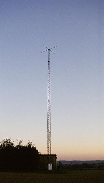
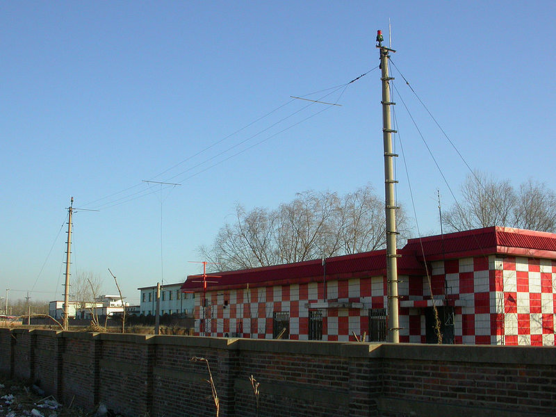
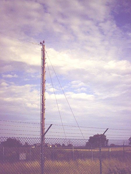
NDBs typically operate in the frequency range from 190 kHz to 535 kHz (although they are allocated frequencies from 190 to 1750 kHz) and transmit a carrier modulated by either 400 or 1020 Hz. NDBs can also be colocated with DME in a similar installation for the ILS as the outer marker, only in this case, they function as the inner marker. NDB owners are mostly governmental agencies and airport authorities. Antennas have as part of their makeup a segment that consists of an inductor and a capacitor in series "tuned" to the particular frequency or frequencies assigned to that antenna. NDB's tuned segment is part of the antenna itself. What is viewed as the Vertical part of the antenna tends to be the supporting pylon for the capacitive element. At low frequencies the antenna itself is capacitive. (functions as the capacitor in the system). There is often a counterpoise (or bottom section of the capacitor) buried in the ground underneath the antenna. The inductive section is the feedline, and the vertical antenna element itself. Other information transmitted by an NDBApart from Morse Code Identity of either 400 Hz or 1020 Hz, the NDB may broadcast:
Common adverse effectsNavigation using an ADF to track NDBs is subject to several common effects:
While pilots study these effects during initial training, trying to compensate for them in flight is very difficult; instead, pilots generally simply choose a heading that seems to average out any fluctuations. Radio-navigation aids must keep a certain degree of accuracy (given by international standards, FAA, ICAO...); to assure this is the case, Flight inspection organizations check periodically critical parameters with properly equipped aircraft to calibrate and certify NDB precision. Monitoring NDBs
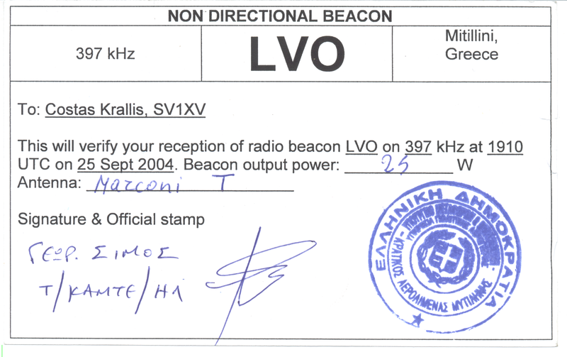
Besides their use in aircraft navigation, NDBs are also popular with long-distance radio enthusiasts ("DXers"). Because NDBs are generally low-power (usually 25 watts), they normally cannot be heard over long distances, but favorable conditions in the ionosphere can allow NDB signals to travel much farther than normal. Because of this, radio DXers interested in picking up distant signals enjoy listening to faraway NDBs. Also, since the band allocated to NDBs is free of broadcast stations and their associated interference, and because most NDBs do little more than transmit their Morse Code callsign, they are very easy to identify, making NDB monitoring a very entertaining niche within the DXing hobby. In North America, the NDB band is from 190 to 435 kHz and from 510 to 530 kHz. In Europe, there is a longwave broadcasting band from 150 to 280 kHz, so the European NDB band is from 280 kHz to 530 kHz with a gap between 495 and 505 kHz because 500 kHz was the international maritime distress (emergency) frequency. The beacons that are between 510 kHz and 530 kHz can sometimes be heard on AM radios that can tune below the beginning of the AM broadcast band. (For example, the "HEH" beacon in Newark, Ohio at 524 kHz is within the bandwidth of most AM radios, and the "OS" beacon in Columbus, Ohio at 515 kHz can also be heard on some AM radios). Some beacons can also be heard on 530 kHz, although from the adjacent frequencies such as "LYQ" at 529 kHz in Manchester, Tennessee but for the most part, reception of NDBs requires a radio receiver that can receive frequencies below 530 kHz (the longwave band). Most so-called "shortwave" radios also include mediumwave and longwave, and they can usually receive all frequencies from 150 kHz to 30 MHz, which makes them ideal for listening to NDBs. Whilst this type of receiver is adequate for reception of local beacons, specialized techniques (receiver preselectors, noise limiters and filters) are required for the reception of very weak signals from remote beacons. The best time to hear NDBs that are very far away (i.e that are "DX") is the last three hours before sunrise. Reception of NDBs is also usually best during the fall and winter because during the spring and summer, there is more atmospheric noise on the LF and MF bands. See also
Text from Wikipedia is available under the Creative Commons Attribution/Share-Alike License; additional terms may apply.
Published in July 2009. Click here to read more articles related to aviation and space!
|

 |
|
Copyright 2004-2026 © by Airports-Worldwide.com, Vyshenskoho st. 36, Lviv 79010, Ukraine Legal Disclaimer |