 |
 |
|
||||
|
By
Wikipedia,
A rocket engine nozzle is a propelling nozzle usually of the de Laval type used in a rocket engine to expand and accelerate the combustion gases, from burning propellants, so that the exhaust gases exit the nozzle at hypersonic velocities. HistoryThe de Laval nozzle was first used in an early rocket engine developed by Robert Goddard, one of the fathers of modern rocketry. Subsequently, almost all rocket engines used this idea, including Walter Thiel's implementation which made possible Germany's V2 rocket. Atmospheric useThe optimal size of a rocket engine nozzle to be used within the atmosphere is when the exit pressure equals ambient pressure, which decreases with altitude. For rockets travelling from the Earth to orbit, a simple nozzle design is only optimal at one altitude, losing efficiency and wasting fuel at other altitudes. If the pressure of the jet leaving the nozzle is above ambient pressure then a nozzle is said to be 'underexpanded'; if the jet is below ambient pressure then it is 'overexpanded'. Slight overexpansion causes a slight reduction in efficiency, but otherwise does little harm. However, if the jet pressure is approximately 40 percent of ambient then 'flow separation' occurs. This can cause jet instabilities that can cause damage to the nozzle or simply cause control difficulties of the vehicle or the engine. In some cases it is desirable for reliability and safety reasons to ignite a rocket engine on the ground that will be used all the way to orbit. In most cases the optimal pressure is ambient, however if most of the thrust comes from (ambient pressure) boosters at takeoff, then the trades push to using an overexpanded nozzle. This is the technique used on the Space shuttle's main engines. Vacuum useFor nozzles that are used in vacuum or at very high altitude, it is impossible to match ambient pressure and rather larger area ratio nozzles are usually more efficient. However, a very long nozzle has significant mass and a length that optimises overall vehicle performance can always be found. Additionally, as the temperature of the gas in the nozzle decreases some components of the exhaust gases (such as water vapour from the combustion process) may liquefy or even freeze. This is highly undesirable and needs to be avoided. Magnetic nozzles have been proposed for some types of propulsion (for example VASIMR), in which the flow of plasma or ions are directed by magnetic fields instead of walls made of solid materials. These can be advantageous since a magnetic field itself cannot melt and the plasma can be at millions of kelvins. But there are often thermal problems in the coils, particularly if superconducting coils are used to form the throat and expansion fields. 1-D Analysis of gas flow in rocket engine nozzles
(Main Article: De Laval nozzle) The analysis of gas flow through de Laval nozzles involves a number of concepts and assumptions:
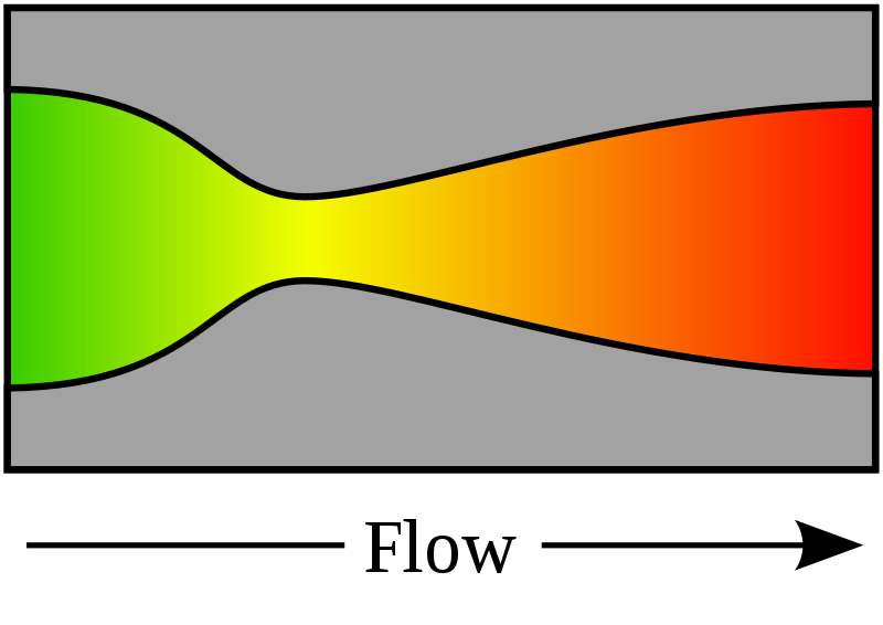
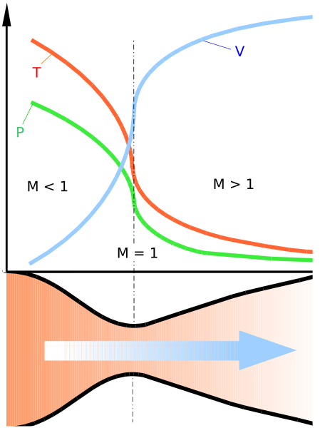
As the combustion gas enters the rocket nozzle, it is traveling at subsonic velocities. As the throat contracts down the gas is forced to accelerate until at the nozzle throat, where the cross-sectional area is the smallest, the linear velocity becomes sonic. From the throat the cross-sectional area then increases, the gas expands and the linear velocity becomes progressively more supersonic. The linear velocity of the exiting exhaust gases can be calculated using the following equation Some typical values of the exhaust gas velocity Ve for rocket engines burning various propellants are:
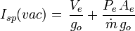
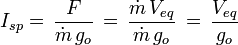
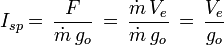
As a note of interest, Ve is sometimes referred to as the ideal exhaust gas velocity because it based on the assumption that the exhaust gas behaves as an ideal gas. As an example calculation using the above equation, assume that the propellant combustion gases are: at an absolute pressure entering the nozzle of P = 7.0 MPa and exit the rocket exhaust at an absolute pressure of Pe = 0.1 MPa; at an absolute temperature of T = 3500 K; with an isentropic expansion factor of k = 1.22 and a molar mass of M = 22 kg/kmol. Using those values in the above equation yields an exhaust velocity Ve = 2802 m/s or 2.80 km/s which is consistent with above typical values. The technical literature can be very confusing because many authors fail to explain whether they are using the universal gas law constant R which applies to any ideal gas or whether they are using the gas law constant Rs which only applies to a specific individual gas. The relationship between the two constants is Rs = R/M. Specific ImpulseThrust is the force which moves a rocket through the air, and through space. Thrust is generated by the propulsion system of the rocket through the application of Newton's third law of motion: "For every action there is an equal and opposite reaction". A gas or working fluid is accelerated out the rear of the rocket engine nozzle and the rocket is accelerated in the opposite direction. The thrust of a rocket engine nozzle can be defined as: and for perfectly expanded nozzles, this reduces to: The specific impulse, Isp, is the ratio of the amount of thrust produced to the weight flow of the propellants. It is a measure of the fuel efficiency of a rocket engine. It can be obtained from: In certain cases, where Pe equals Po, then: In cases where this may not be the case since for a rocket nozzle Pe is proportional to and hence: which is simply the vacuum thrust minus the force of the ambient atmospheric pressure acting over the exit plane. Essentially then, for rocket nozzles, the ambient pressure acting over the engine largely cancels but effectively acts over the exit plane of the rocket engine in a rearward direction, while the exhaust jet generates forward thrust.
Aerostatic back-pressure and optimum expansionAs the gas travels down the expansion part of the nozzle the pressure and temperature decreases and the speed of the gas increases. The supersonic nature of the exhaust jet means that the pressure of the exhaust can be significantly different from ambient pressure- the outside air is unable to equalize the pressure upstream due to the very high jet velocity. Therefore, for supersonic nozzles, it is actually possible for the pressure of the gas exiting the nozzle to go significantly below or very greatly above ambient pressure. If the exit pressure is too low, then the jet can separate from the nozzle. This is often unstable and the jet will generally cause large off-axis thrusts, and may mechanically damage the nozzle. This separation generally occurs if the exit pressure goes below roughly 30-45% of ambient, but may be delayed to far lower pressures if the nozzle is designed to increase the pressure at the rim, as is achieved with the SSME (1-2 psi at 15 psi ambient). Other things also very modestly affect the efficiency of a rocket nozzle, it's important that the throat be a smooth radius, the angle of the narrowing down to the throat also has a very slight affect on the overall efficiency, but this is small. The exit of the nozzle needs to be as sharp as possible to minimize the chances of separation problems at low exit pressures. Advanced designsA number of more sophisticated designs have been proposed and they can be categorised by the method with which they achieve altitude compensation. Nozzles with an atmospheric boundary include:
Each of these allows the supersonic flow to adapt to the ambient pressure by expanding or contracting, thereby changing the exit ratio so that it is at (or near) optimal exit pressure for the corresponding altitude. The plug and aerospike nozzles are very similar in that they are radial in-flow designs but plug nozzles feature a solid centrebody (sometimes truncated) and aerospike nozzles have a 'base-bleed' of gases to simulate a solid centre-body. ED nozzles are radial out-flow nozzles with the flow deflected by a centre pintle. Controlled flow-separation nozzles include:
These are generally very similar to bell nozzles but include an insert or mechanism by which the exit area ratio can be increased as ambient pressure is reduced. Dual-mode nozzles include:
These have either two throats or two thrust chamber (with corresponding throats). The central throat is of a standard design but it is surrounded by an annular throat which exhausts gases from the same (dual-throat) or a separate (dual-expander) thrust chamber. Both throats would, in either case, discharge into a bell nozzle. At higher altitues where the ambient pressure is lower, the central nozzle would be shut off reducing the throat area and thereby increasing the nozzle area ratio. These designs require additional complexity but an advantage of having two thrust chambers is that they can be configured to burn different propellants or different fuel mixture ratios. Similarly, Aerojet has also designed a nozzle called the 'Thrust Augmented Nozzle' which injects propellant and oxidiser directly into the nozzle section for combustion allowing larger area ratio nozzles to be used deeper in an atmosphere than they would without augmentation due to effects of flow separation. They would again allow multiple propellants to be used (such as RP-1) further increasing thrust. There is also a SERN (Single Expansion Ramp Nozzle), a linear expansion nozzle where the gas pressure transfers work only on one side and which could be described as a single-sided aerospike nozzle. See also
Text from Wikipedia is available under the Creative Commons Attribution/Share-Alike License; additional terms may apply.
Published in July 2009. Click here to read more articles related to aviation and space!
|

 |
|
Copyright 2004-2026 © by Airports-Worldwide.com, Vyshenskoho st. 36, Lviv 79010, Ukraine Legal Disclaimer |
![V_e = \sqrt{\;\frac{T\;R}{M}\cdot\frac{2\;k}{k-1}\cdot\bigg[ 1-(P_e/P)^{(k-1)/k}\bigg]}](../img/wikipedia/0665-formula-01.png)
 , then it is possible to define a constant quantity which is the vacuum