 |
 |
|
||||
|
By
Wikipedia, A viscometer (also called viscosimeter) is an instrument used to measure the viscosity of a fluid. For liquids with viscosities which vary with flow conditions, an instrument called a rheometer is used. Viscometers only measure under one flow condition. In general, either the fluid remains stationary and an object moves through it, or the object is stationary and the fluid moves past it. The drag caused by relative motion of the fluid and a surface is a measure of the viscosity. The flow conditions must have a sufficiently small value of Reynolds number for there to be laminar flow. At 20.00 degrees Celsius the viscosity of water is 1.002 mPa·s and its kinematic viscosity (ratio of viscosity to density) is 1.0038 mm/s. These values are used for calibrating certain types of viscometer. Standard laboratory viscometers for liquids
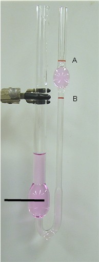
U-tube viscometersThese are also known as Ostwald viscometers named after Wilhelm Ostwald or glass capillary viscometers. Another type is the Ubbelohde viscometer. They basically consist of a glass tube in the shape of a U held vertically in a controlled temperature bath. In one arm of the U is a vertical section of precise narrow bore (the capillary). Above this is a bulb, there is another bulb lower down in the other arm. In use, liquid is drawn into the upper bulb by suction, then allowed to flow down through the capillary into the lower bulb. Two marks (one above and one below the upper bulb) indicate a known volume. The time taken for the level of the liquid to pass between these marks is proportional to the kinematic viscosity. Most commercial units are provided with a conversion factor, or can be calibrated by a fluid of known properties. The time it takes for the test liquid to flow through a capillary of a known diameter of a certain factor between 2 marked points is measured. By multiplying the time taken by the factor of the viscometer, the kinematic viscosity is obtained. The viscometers are usually placed in a constant temperature water bath as temperature affects viscosity. Such viscometers are also classified as direct flow or reverse flow. Reverse flow viscometers have the reservoir above the markings and direct flow are those with the reservoir below the markings. Such classifications exists so that the level can be determined even when opaque or staining liquids are measured, otherwise the liquid will cover the markings and make it impossible to gauge the time the level passes the mark. This also allows the viscometer to have more than 1 set of marks to allow for an immediate timing of the time it takes to reach the 3rd mark, therefore yielding 2 timings and allowing for subsequent calculation of Determinability to ensure accurate results. Falling sphere viscometers
Stokes' law is the basis of the falling sphere viscometer, in which the fluid is stationary in a vertical glass tube. A sphere of known size and density is allowed to descend through the liquid. If correctly selected, it reaches terminal velocity, which can be measured by the time it takes to pass two marks on the tube. Electronic sensing can be used for opaque fluids. Knowing the terminal velocity, the size and density of the sphere, and the density of the liquid, Stokes' law can be used to calculate the viscosity of the fluid. A series of steel ball bearings of different diameter is normally used in the classic experiment to improve the accuracy of the calculation. The school experiment uses glycerine as the fluid, and the technique is used industrially to check the viscosity of fluids used in processes. It includes many different oils, and polymer liquids such as solutions. In 1851, George Gabriel Stokes derived an expression for the frictional force (also called drag force) exerted on spherical objects with very small Reynolds numbers (e.g., very small particles) in a continuous viscous fluid by solving the small fluid-mass limit of the generally unsolvable Navier-Stokes equations: where:
If the particles are falling in the viscous fluid by their own weight, then a terminal velocity, also known as the settling velocity, is reached when this frictional force combined with the buoyant force exactly balance the gravitational force. The resulting settling velocity (or terminal velocity) is given by: where:
Note that Stokes flow is assumed, so the Reynolds number must be small. A limiting factor on the validity of this result is the Roughness of the sphere being used. Falling Piston ViscometerAlso known as Norcross viscometer due to inventor, Austin Norcross. Principle of viscosity measurement in this rugged and sensitive industrial device is based on piston and cylinder assembly. Piston is periodically raised by an air lifting mechanism, drawing the material being measured down through the clearance(gap)between the piston and the wall of the cylinder into the space which is formed below the piston as it is raised. The assembly is then held up for typically for few seconds. The assembly is then allowed to fall by gravity, expelling the sample out through the same path as it entered, creating a shearing effect on measured liquid, which makes this viscometer particularly sensitive and good for measuring certain thixotropic liquids. The time of fall is a measure of viscosity, with the clearance between the piston and inside of the cylinder forming the measuring orifice. The viscosity controller measures the time of fall (Time-of-fall seconds being measure of viscosity) and displays the resulting viscosity value. Controller can calibrate time-of-fall value to cup seconds(known efflux cup), SSU or centipoise. Vibrational viscometersVibrational viscometers date back to the 1950s Bendix instrument, which is of a class that operates by measuring the damping of an oscillating electromechanical resonator immersed in a fluid whose viscosity is to be determined. The resonator generally oscillates in torsion or transversely (as a cantilever beam or tuning fork). The higher the viscosity, the larger the damping imposed on the resonator. The resonator's damping may be measured by one of several methods:
The vibrational instrument also suffers from a lack of a defined shear field, which makes it unsuited to measuring the viscosity of a fluid whose flow behaviour is not known before hand. Vibrating viscometers are rugged industrial systems used to measure viscosity in the process condition. The active part of the sensor is a vibrating rod. The vibration amplitude varies according to the viscosity of the fluid in which the rod is immersed. These viscosity meters are suitable for measuring clogging fluid and high-viscosity fluids, including those with fibers (up to 1,000 Pa·s). Currently, many industries around the world consider these viscometers to be the most efficient system with which to measure the viscosities of a wide range of fluids; by contrast, rotational viscometers require more maintenance, are unable to measure clogging fluid, and require frequent calibration after intensive use. Vibrating viscometers have no moving parts, no weak parts and the sensitive part is very small. Even very basic or acidic fluids can be measured by adding a protective coating or by changing the material of the sensor to a material such as 316L, SUS316, Hastelloy, or enamel. Rotational viscometersRotational viscometers use the idea that the torque required to turn an object in a fluid is a function of the viscosity of that fluid. They measure the torque required to rotate a disk or bob in a fluid at a known speed. 'Cup and bob' viscometers work by defining the exact volume of a sample which is to be sheared within a test cell; the torque required to achieve a certain rotational speed is measured and plotted. There are two classical geometries in "cup and bob" viscometers, known as either the "Couette" or "Searle" systems - distinguished by whether the cup or bob rotates. The rotating cup is preferred in some cases because it reduces the onset of Taylor vortices, but is more difficult to measure accurately. 'Cone and Plate' viscometers use a cone of very shallow angle in bare contact with a flat plate. With this system the shear rate beneath the plate is constant to a modest degree of precision and deconvolution of a flow curve; a graph of shear stress (torque) against shear rate (angular velocity) yields the viscosity in a straightforward manner. Stabinger viscometer
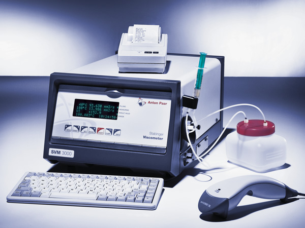
By modifying the classic Couette rotational viscometer, an accuracy comparable to that of kinematic viscosity determination is achieved. The internal cylinder in the Stabinger Viscometer is hollow and specifically lighter than the sample, thus floats freely in the sample, centered by centrifugal forces. The formerly inevitable bearing friction is thus fully avoided. The speed and torque measurement is implemented without direct contact by a rotating magnetic field and an eddy current brake. This allows for a previously unprecedented torque resolution of 50 pN·m and an exceedingly large measuring range from 0.2 to 20,000 mPa·s with a single measuring system. A built-in density measurement based on the oscillating U-tube principle allows the determination of kinematic viscosity from the measured dynamic viscosity employing the relation The Stabinger Viscometer was presented for the first time by Anton Paar GmbH at the ACHEMA in the year 2000. The measuring principle is named after its inventor Dr. Hans Stabinger. Stormer viscometerThe Stormer viscometer is a rotation instrument used to determine the viscosity of paints, commonly used in paint industries. It consists of a paddle-type rotor that is spun by an internal motor, submerged into a cylinder of viscous substance. The rotor speed can be adjusted by changing the amount of load supplied onto the rotor. For example, in one brand of viscometers, pushing the level upwards decreases the load and speed, downwards increases the load and speed. The viscosity can be found by adjusting the load until the rotation velocity is 200 rotations per minute. By examining the load applied and comparing tables found on ASTM D 562, one can find the viscosity in Krebs units (KU), unique only to the Stormer type viscometer. This method is intended for paints applied by brush or roller. Bubble viscometerBubble viscometers are used to quickly determine kinematic viscosity of known liquids such as resins and varnishes. The time required for an air bubble to rise is inversely proportional to the visosity of the liquid, so the faster the bubble rises, the lower the viscosity. The Alphabetical Comparison Method uses 4 sets of lettered reference tubes, A5 through Z10, of known viscosity to cover a viscosity range from 0.005 to 1,000 stokes. The Direct Time Method uses a single 3-line times tube for determining the "bubble seconds", which may then be converted to stokes. Miscellaneous viscometer typesOther viscometer types use balls or other objects. Viscometers that can characterize non-Newtonian fluids are usually called rheometers or plastometers. In the I.C.I "Oscar" viscometer, a sealed can of fluid was oscillated torsionally, and by clever measurement techniques it was possible to measure both viscosity and elasticity in the sample. See also
External links
Text from Wikipedia is available under the Creative Commons Attribution/Share-Alike License; additional terms may apply.
Published in July 2009. Click here to read more articles related to aviation and space!
|

 |
|
Copyright 2004-2026 © by Airports-Worldwide.com, Vyshenskoho st. 36, Lviv 79010, Ukraine Legal Disclaimer |