 |
 |
|
||||
|
By
Wikipedia,
A railgun is a purely electrical gun that accelerates a conductive projectile along a pair of metal rails using the same principles as the homopolar motor. Railguns use two sliding or rolling contacts that permit a large electric current to pass through the projectile. This current interacts with the strong magnetic fields generated by the rails and this accelerates the projectile. The U.S. Navy has tested a railgun that accelerates a 7 pound projectile to seven times the speed of sound. Railguns should not be confused with:
History
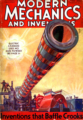
In 1918, French inventor Louis Octave Fauchon-Villeplee invented an electric cannon which bears a strong resemblance to the linear motor. He filed for a US patent on 1 April 1919, which was issued in July 1922 as patent no. 1,421,435 "Electric Apparatus for Propelling Projectiles". In his device, two parallel busbars are connected by the wings of a projectile, and the whole apparatus surrounded by a magnetic field. By passing current through busbars and projectile, a force is induced which propels the projectile along the bus-bars and into flight. During World War II the idea was revived by Joachim Hänsler of Germany's Ordnance Office, and an electric anti-aircraft gun was proposed. By late 1944 enough theory had been worked out to allow the Luftwaffe's Flak Command to issue a specification, which demanded a muzzle velocity of 2,000 m/s (6,600 ft/s) and a projectile containing 0.5 kg (1.1 lb) of explosive. The guns were to be mounted in batteries of six firing twelve rounds per minute, and it was to fit existing 12.8 cm FlaK 40 mounts. It was never built. When details were discovered after the war it aroused much interest and a more detailed study was carried out, culminating in a 1947 report which concluded that it was theoretically feasible, but that each gun would need enough power to illuminate half of Chicago. In 1950, Sir Mark Oliphant, an Australian physicist and first director of the Research School of Physical Sciences at the new Australian National University, initiated the design and construction of the world's largest (500MJ) homopolar generator. This machine was used to power the large-scale railgun which was used as a scientific instrument. Theory and construction
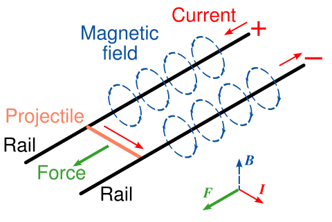
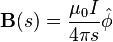
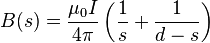
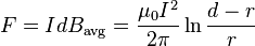
A railgun consists of two parallel metal rails (hence the name) connected to an electrical power supply. When a conductive projectile is inserted between the rails (from the end connected to the power supply), it completes the circuit. Electrons flow from the negative terminal of the power supply up the negative rail, across the projectile, and down the positive rail, back to the power supply. This current makes the railgun behave as an electromagnet, creating a powerful magnetic field in the region of the rails up to the position of the projectile. In accordance with the right-hand rule, the magnetic field circulates around each conductor. Since the current is in opposite direction along each rail, the net magnetic field between the rails (B) is directed vertically. In combination with the current (I) across the projectile, this produces a Lorentz force which accelerates the projectile along the rails. There are also forces acting on the rails attempting to push them apart, but since the rails are firmly mounted, they cannot move. The projectile slides up the rails away from the end with the power supply. A very large power supply providing, on the order of, one million amperes of current will create a tremendous force on the projectile, accelerating it to a speed of many kilometres per second (km/s). 20 km/s has been achieved with small projectiles explosively injected into the railgun. Although these speeds are theoretically possible, the heat generated from the propulsion of the object is enough to rapidly erode the rails. Such a railgun would require frequent replacement of the rails, or use a heat resistant material that would be conductive enough to produce the same effect. Considerations in railgun designMaterialsThe rails and projectiles must be built from strong conductive materials; the rails need to survive the violence of an accelerating projectile, and heating due to the large currents and friction involved. The recoil force exerted on the rails is equal and opposite to the force propelling the projectile. The seat of the recoil force is still debated. The traditional equations predict that the recoil force acts on the breech of the railgun. Another school of thought invokes Ampère's force law and asserts that it acts along the length of the rails (which is their strongest axis). The rails also repel themselves via a sideways force caused by the rails being pushed by the magnetic field, just as the projectile is. The rails need to survive this without bending, and must be very securely mounted. Design considerationsThe power supply must be able to deliver large currents, sustained and controlled over a useful amount of time. The most important gauge of power supply effectiveness is the energy it can deliver. As of February 2008, the largest known energy used to propel a projectile from a railgun was 32 million joules. The most common forms of power supplies used in railguns are capacitors and compulsators which are slowly charged from other continuous energy sources. The rails need to withstand enormous repulsive forces during firing, and these forces will tend to push them apart and away from the projectile. As rail/projectile clearances increase, arcing develops, which causes rapid vaporization and extensive damage to the rail surfaces and the insulator surfaces. This limited some early research railguns to one shot per service interval. The inductance and resistance of the rails and power supply limit the efficiency of a railgun design. Currently different rail shapes and railgun configurations are being tested, most notably by the United States Navy, The Institute for Advanced Technology, and BAE Systems. Heat dissipationMassive amounts of heat are created by the electricity flowing through the rails, as well as by the friction of the projectile leaving the device. The heat created by this friction itself can cause thermal expansion of the rails and projectile, further increasing the frictional heat. This leads to three main problems: melting of equipment, safety of personnel, and detection by enemy forces. As briefly discussed above, the stresses involved in firing this sort of device require an extremely heat-resistant material. Otherwise the rails, barrel, and all equipment attached would melt or be irreparably damaged. In practice the rails are, with most designs of railgun, subject to erosion due to each launch; and projectiles can be subject to some degree of ablation also, and this can limit railgun life, in some cases severely. Mathematical formulaIn railgun physics, the magnitude of the force vector can be determined from a form of the Biot-Savart Law and a result of the Lorentz force. It can be derived mathematically in terms of the permeability constant (μ0), the radius of the rails (which are assumed to be circular in cross section) (r), the distance between the centerpoints of the rails (d) and the current in amps through the system (I) as follows: So, in the space between two semi-infinite wires, the magnitude of the field is: To obtain the average magnetic field in the space between the two wires, we assume that r is small compared with d and compute the following integral: By the Lorentz force law, the magnetic force on a current-carrying wire is given by IdB, so since the width of the conductive projectile is d, we have The formula is based on the assumption that the distance (l) between the point where the force (F) is measured and the beginning of the rails is greater than the separation of the rails (d) by a factor of about 3 or 4 (l > 3d). Some other simplifying assumptions have also been made; to describe the force more accurately, the geometry of the rails and the projectile must be taken into consideration. In rocketryElectrodynamic assistance to launch rockets has been studied. Space applications of this technology involve specially formed electromagnetic coils and superconducting magnets. Composite materials are used for this application. Railguns as weapons
Railguns are being pursued as weapons with projectiles that do not contain explosives, but are given extremely high velocities: 3500 m/s (11,500 ft/s, approximately Mach 10 at sea level) or more (for comparison, the M16 rifle has a muzzle speed of 930 m/s, or 3,000 ft/s), which would make their kinetic energy equal or superior to the energy yield of an explosive-filled shell of greater mass. This would allow more ammunition to be carried and eliminate the hazards of carrying explosives in a tank or naval weapons platform. Also, by firing at higher velocities railguns have greater range, less bullet drop and less wind drift, bypassing the inherent cost and physical limitations of conventional firearms - "the limits of gas expansion prohibit launching an unassisted projectile to velocities greater than about 1.5 km/s and ranges of more than 50 miles [80 km] from a practical conventional gun system." If it were possible to apply the technology as a rapid-fire automatic weapon, a railgun would have further advantages in increased rate of fire. The feed mechanisms of a conventional firearm must move to accommodate the propellant charge as well as the ammunition round, while a railgun would only need to accommodate the projectile. Furthermore, a railgun would not have to extract a spent cartridge case from the breech, meaning that a fresh round could be cycled almost immediately after the previous round has been shot. Tests
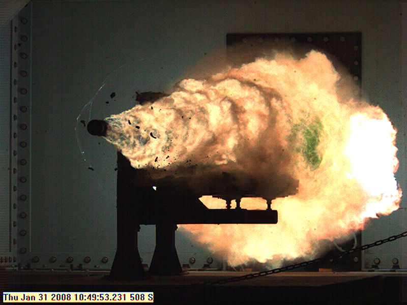
Full-scale models have been built and fired, including a very successful 90 mm bore, 9 MJ kinetic energy gun developed by the US DARPA. Rail and insulator wear issues still need to be addressed before railguns can start to replace conventional weapons. Probably the oldest consistently successful system was built by the UK's Defence Research Agency at Dundrennan Range in Kirkcudbright, Scotland. This system has now been operational for over 10 years at an associated flight range for internal, intermediate, external and terminal ballistics, and achieved several mass and velocity records. The Serbian VTI (MTI - Military - technology institute) developed, within a project named EDO-0, a rail gun with 7 kJ kinetic energy, in 1985. In 1987 a successor was created, project EDO-1, that used projectile with a mass of 0.7 g and achieved speeds of 3000 m/s, and with a mass of 1.1 g reached speeds of 2400 m/s. It used a track length of 0.7 m. According to those working on it, with other modifications it was able to achieve a speed of 4500 m/s. The aim was to achieve projectile speed of 7000 m/s. At the time, it was considered a military secret. The United States military is funding railgun experiments. At the University of Texas at Austin Institute for Advanced Technology, military railguns capable of delivering tungsten armor piercing bullets with kinetic energies of nine megajoules have been developed. 9 MJ is enough energy to deliver 2 kg of projectile at 3 km/s - at that velocity a rod of tungsten or of another dense metal could easily penetrate a tank, and potentially pass through it. The United States Naval Surface Warfare Center Dahlgren Division demonstrated an 8 MJ rail gun firing 3.2 kg projectiles in October 2006 as a prototype of a 64 MJ weapon to be deployed aboard Navy warships. The main problem the Navy has had with implementing a railgun cannon system is that the guns wear out due to the immense heat produced by firing. Such weapons are expected to be powerful enough to do a little more damage than a BGM-109 Tomahawk missile at a fraction of the projectile cost. Since then, BAE Systems has delivered a 32 MJ prototype to the Navy. Due to the very high muzzle velocity that can be attained with railguns, there is interest in using them to shoot down high-speed missiles. On January 31, 2008 the US Navy tested a railgun; it fired a shell at 2520 m/s with an energy of 10.64 MJ. Its expected performance is over 5.8 km/s muzzle velocity, accurate enough to hit a 5 meter target from 200 nautical miles (370 km) away while shooting at 10 shots per minute. It is expected to be ready in 2020 to 2025.[1] See also
Text from Wikipedia is available under the Creative Commons Attribution/Share-Alike License; additional terms may apply.
Published in July 2009. Click here to read more articles related to aviation and space!
|

 |
|
Copyright 2004-2026 © by Airports-Worldwide.com, Vyshenskoho st. 36, Lviv 79010, Ukraine Legal Disclaimer |