 |
 |
|
||||
|
By
Wikipedia, Flight dynamics is the science of air and space vehicle orientation and control in three dimensions. The three critical flight dynamics parameters are the angles of rotation in three dimensions about the vehicle's center of mass, known as pitch, roll and yaw. Aerospace engineers develop control systems for a vehicle's orientation (attitude) about its center of mass. The control systems include actuators, which exert forces in various directions, and generate rotational forces or moments about the aerodynamic center of the aircraft, and thus rotate the aircraft in pitch, roll, or yaw. For example, a pitching moment is a vertical force applied at a distance forward or aft from the aerodynamic center of the aircraft, causing the aircraft to pitch up or down. Roll, pitch and yaw refer to rotations about the respective axes starting from a defined equilibrium state. The equilibrium roll angle is known as wings level or zero bank angle, equivalent to a level heeling angle on a ship. Yaw is known as 'heading'. The equilibrium pitch angle in submarine and airship parlance is known as 'trim', but in aircraft, this usually refers to angle of attack, rather than orientation. However, common usage ignores this distinction between equilibrium and dynamic cases. The most common aeronautical convention defines the roll as acting about the longitudinal axis, positive with the starboard(right) wing down. The yaw is about the vertical body axis, positive with the nose to starboard. Pitch is about an axis perpendicular to the longitudinal plane of symmetry, positive nose up. A fixed-wing aircraft increases or decreases the lift generated by the wings when it pitches nose up or down by increasing or decreasing the angle of attack (AOA). The roll angle is also known as bank angle on a fixed wing aircraft, which usually "banks" to change the horizontal direction of flight. An aircraft is usually streamlined from nose to tail to reduce drag making it typically advantageous to keep the sideslip angle near zero, though there are instances when an aircraft may be deliberately "sideslipped" for example a slip in a fixed wing aircraft. Coordinate systemsThe position (and hence motion) of an aircraft is generally defined relative to one of 3 sets of co-ordinate systems:
For flight dynamics applications the Earth Axes are generally of minimal use, and hence will be ignored. The motions relevant to dynamic stability are usually too short in duration for the motion of the Earth itself to be considered relevant for aircraft. In flight dynamics, pitch, roll and yaw angles measure both the absolute attitude angles (relative to the horizon/North) and changes in attitude angles, relative to the equilibrium orientation of the vehicle. These are defined as:
In analysing the dynamics, we are concerned both with rotation and translation of this axis set with respect to a fixed inertial frame. For all practical purposes a local Earth axis set is used, this has X and Y axis in the local horizontal plane, usually with the x-axis coinciding with the projection of the velocity vector at the start of the motion, on to this plane. The z axis is vertical, pointing generally towards the Earth's centre, completing an orthogonal set. In general, the body axes are not aligned with the Earth axes. The body orientation may be defined by three Euler angles, the Tait-Bryan rotations, a quaternion, or a direction cosine matrix (rotation matrix). A rotation matrix is particularly convenient for converting velocity, force, angular velocity, and torque vectors between body and Earth coordinate frames. Body axes tend to be used with missile and rocket configurations. Aircraft stability uses wind axes in which the x-axis points along the velocity vector. For straight and level flight this is found from body axes by rotating nose down through the angle of attack. Stability deals with small perturbations in angular displacements about the orientation at the start of the motion. This consists of two components; rotation about each axis, and angular displacements due change in orientation of each axis. The latter term is of second order for the purpose of stability analysis, and is ignored. Design casesIn analysing the stability of an aircraft, it is usual to consider perturbations about a nominal equilibrium position. So the analysis would be applied, for example, assuming:
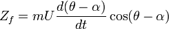
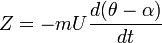
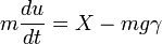
The speed, height and trim angle of attack are different for each flight condition, in addition, the aircraft will be configured differently, e.g. at low speed flaps may be deployed and the undercarriage may be down. Except for asymmetric designs (or symmetric designs at significant sideslip), the longitudinal equations of motion (involving pitch and lift forces) may be treated independently of the lateral motion (involving roll and yaw). The following considers perturbations about a nominal straight and level flight path. To keep the analysis (relatively) simple, the control surfaces are assumed fixed throughout the motion, this is stick-fixed stability. Stick-free analysis requires the further complication of taking the motion of the control surfaces into account. Furthermore, the flight is assumed to take place in still air, and the aircraft is treated as a rigid body. SpacecraftUnless designed to conduct part of the mission within a planetary atmosphere, a spacecraft would generally have no discernible front or side, and no bottom unless designed to land on a surface, so reference to a 'nose' or 'wing' or even 'down' is arbitrary. On a manned spacecraft, the axes must be oriented relative to the pilot's physical orientation at the flight control station. Unmanned spacecraft may need to maintain orientation of solar cells toward the Sun, antennas toward the Earth, or cameras toward a target, so the axes will typically be chosen relative to these functions. Longitudinal modesIt is common practice to derive a fourth order characteristic equation to describe the longitudinal motion, and then factorise it approximately into a high frequency mode and a low frequency mode. This requires a level of algebraic manipulation which most readers will doubtless find tedious, and adds little to the understanding of aircraft dynamics. The approach adopted here is to use our qualitative knowledge of aircraft behaviour to simplify the equations from the outset, reaching the same result by a more accessible route. The two longitudinal motions (modes) are called the short period pitch oscillation (SSPO), and the phugoid. Short-period pitch oscillationA short input (in control systems terminology an impulse) in pitch (generally via the elevator in a standard configuration fixed wing aircraft) will generally lead to overshoots about the trimmed condition. The transition is characterised by a damped simple harmonic motion about the new trim. There is very little change in the trajectory over the time it takes for the oscillation to damp out. Generally this oscillation is high frequency (hence short period) and is damped over a period of a few seconds. A real-world example would involve a pilot selecting a new climb attitude, for example 5º nose up from the original attitude. A short, sharp pull back on the control column may be used, and will generally lead to oscillations about the new trim condition. If the oscillations are poorly damped the aircraft will take a long period of time to settle at the new condition, potentially leading to Pilot-induced oscillation. If the short period mode is unstable it will generally be impossible for the pilot to safely control the aircraft for any period of time. This damped harmonic motion is called the short period pitch oscillation, it arises from the tendency of a stable aircraft to point in the general direction of flight. It is very similar in nature to the weathercock mode of missile or rocket configurations. The motion involves mainly the pitch attitude θ (theta) and incidence α (alpha). The direction of the velocity vector, relative to inertial axes is θ − α. The velocity vector is:
where uf,wf are the inertial axes components of velocity. According to Newton's Second Law, the accelerations are proportional to the forces, so the forces in inertial axes are: where m is the mass. By the nature of the motion, the speed variation But the forces are generated by the pressure distribution on the body, and are referred to the velocity vector. But the velocity (wind) axes set is not an inertial frame so we must resolve the fixed axes forces into wind axes. Also, we are only concerned with the force along the z-axis:
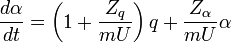
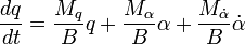
Or: In words, the wind axes force is equal to the centripetal acceleration. The moment equation is the time derivative of the angular momentum: where M is the pitching moment, and B is the moment of inertia about the pitch axis. Let: We are only concerned with perturbations in forces and moments, due to perturbations in the states α and q, and their time derivatives. These are characterised by stability derivatives determined from the flight condition. The possible stability derivatives are:
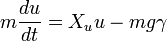
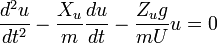
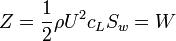
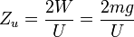
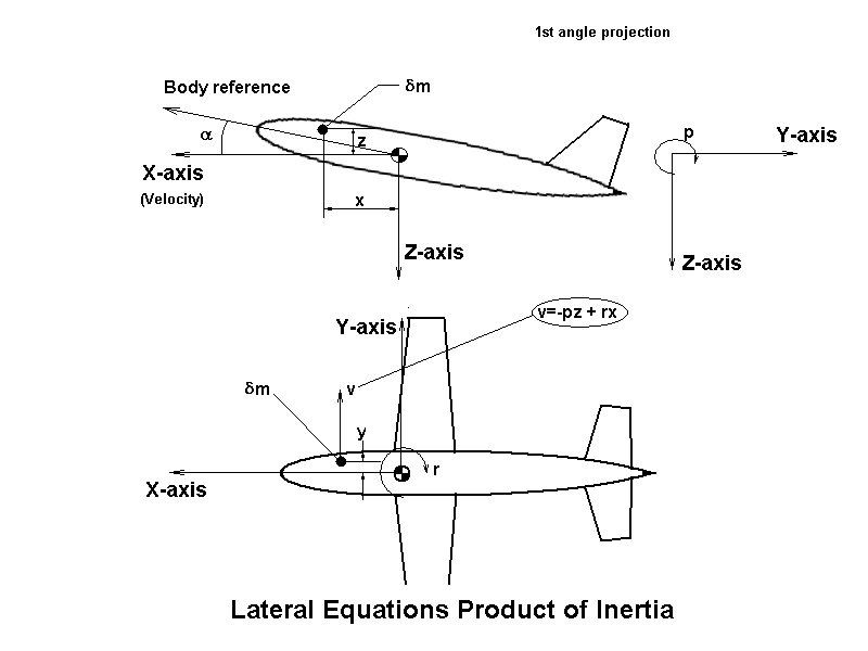
Since the tail is operating in the flowfield of the wing, changes in the wing incidence cause changes in the downwash, but there is a delay for the change in wing flowfield to affect the tail lift, this is represented as a moment proportional to the rate of change of incidence: Increasing the wing incidence without increasing the tail incidence produces a nose up moment, so The equations of motion, with small perturbation forces and moments become: These may be manipulated to yield as second order linear differential equation in α: This represents a damped simple harmonic motion. We should expect PhugoidIf the stick is held fixed, the aircraft will not maintain straight and level flight, but will start to dive, level out and climb again. It will repeat this cycle until the pilot intervenes. This long period oscillation in speed and height is called the phugoid mode. This is analysed by assuming that the SSPO performs its proper function and maintains the angle of attack near its nominal value. The two states which are mainly affected are the climb angle γ (gamma) and speed. The small perturbation equations of motion are: which means the centripetal force is equal to the perturbation in lift force. For the speed, resolving along the trajectory: where g is the acceleration due to gravity at the earths surface. The acceleration along the trajectory is equal to the net x-wise force minus the component of weight. We should not expect significant aerodynamic derivatives to depend on the climb angle, so only Xu and Zu need be considered. Xu is the drag increment with increased speed, it is negative, likewise Zu is the lift increment due to speed increment, it is also negative because lift acts in the opposite sense to the z-axis. The equations of motion become: These may be expressed as a second order equation in climb angle or speed perturbation: Now lift is very nearly equal to weight: where ρ is the air density, Sw is the wing area, W the weight and cL is the lift coefficient (assumed constant because the incidence is constant), we have, approximately: The period of the phugoid, T, is obtained from the coefficient of u: Or: Since the lift is very much greater than the drag, the phugoid is at best lightly damped. A propeller with fixed speed would help. Heavy damping of the pitch rotation or a large rotational inertia increase the coupling between short period and phugoid modes, so that these will modify the phugoid. Lateral modesWith a symmetrical rocket or missile, the directional stability in yaw is the same as the pitch stability; it resembles the short period pitch oscillation, with yaw plane equivalents to the pitch plane stability derivatives. For this reason pitch and yaw directional stability are collectively known as the 'weathercock' stability of the missile. Aircraft lack the symmetry between pitch and yaw, so that directional stability in yaw is derived from a different set of stability derivatives, The yaw plane equivalent to the short period pitch oscillation, which describes yaw plane directional stability is called Dutch roll. Unlike pitch plane motions, the lateral modes involve both roll and yaw motion. Dutch rollIt is customary to derive the equations of motion by formal manipulation in what, to the engineer, amounts to a piece of mathematical sleight of hand. The current approach follows the pitch plane analysis in formulating the equations in terms of concepts which are reasonably familiar. Applying an impulse via the rudder pedals should induce Dutch roll, which is the oscillation in roll and yaw, with the roll motion lagging yaw by a quarter cycle, so that the wing tips follow elliptical paths with respect to the aircraft. The yaw plane translational equation, as in the pitch plane, equates the centripetal acceleration to the side force. where β (beta) is the sideslip angle, Y the side force and r the yaw rate. The moment equations are a bit trickier. The trim condition is with the aircraft at an angle of attack with respect to the airflow, The body x-axis does not align with the velocity vector, which is the reference direction for wind axes. In other words, wind axes are not principal axes (the mass is not distributed symmetrically about the yaw and roll axes). Consider the motion of an element of mass in position -z,x in the direction of the y-axis, i.e. into the plane of the paper. If the roll rate is p, the velocity of the particle is:
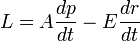
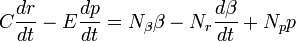
Made up of two terms, the force on this particle is first the proportional to rate of v change, the second is due to the change in direction of this component of velocity as the body moves. The latter terms gives rise to cross products of small quantities (pq,pr,qr), which are later discarded. In this analysis, they are discarded from the outset for the sake of clarity. In effect, we assume that the direction of the velocity of the particle due to the simultaneous roll and yaw rates does not change significantly throughout the motion. With this simplifying assumption, the acceleration of the particle becomes: The yawing moment is given by: There is an additional yawing moment due to the offset of the particle in the y direction: The yawing moment is found by summing over all particles of the body: where N is the yawing moment, E is a product of inertia, and C is the moment of inertia about the yaw axis. A similar reasoning yields the roll equation: where L is the rolling moment and A the roll moment of inertia. Lateral and longitudinal stability derivativesThe states are β (sideslip),r (yaw rate) and p (roll rate), with moments N (yaw) and L (roll), and force Y (sideways). There are nine stability derivatives relevant to this motion, the following explains how they originate. However a better intuitive understanding is to be gained by simply playing with a model aeroplane, and considering how the forces on each component are affected by changes in sideslip and angular velocity:
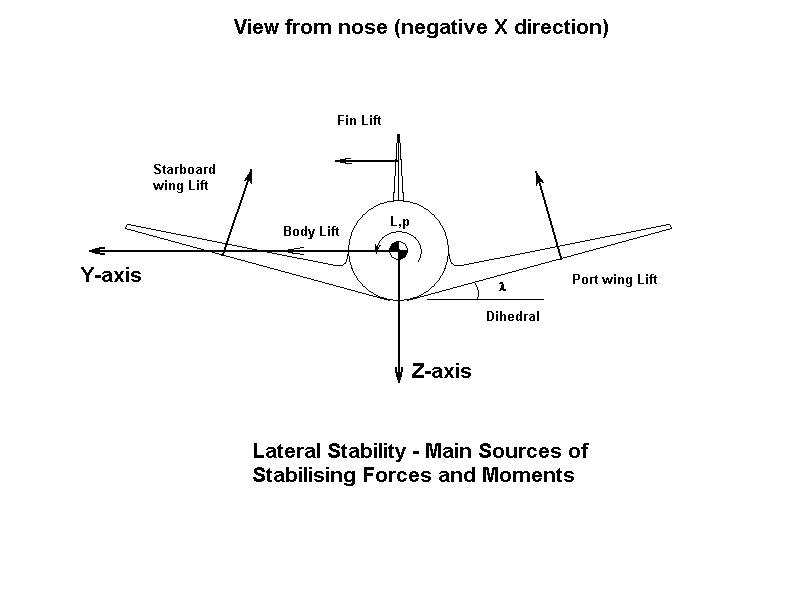
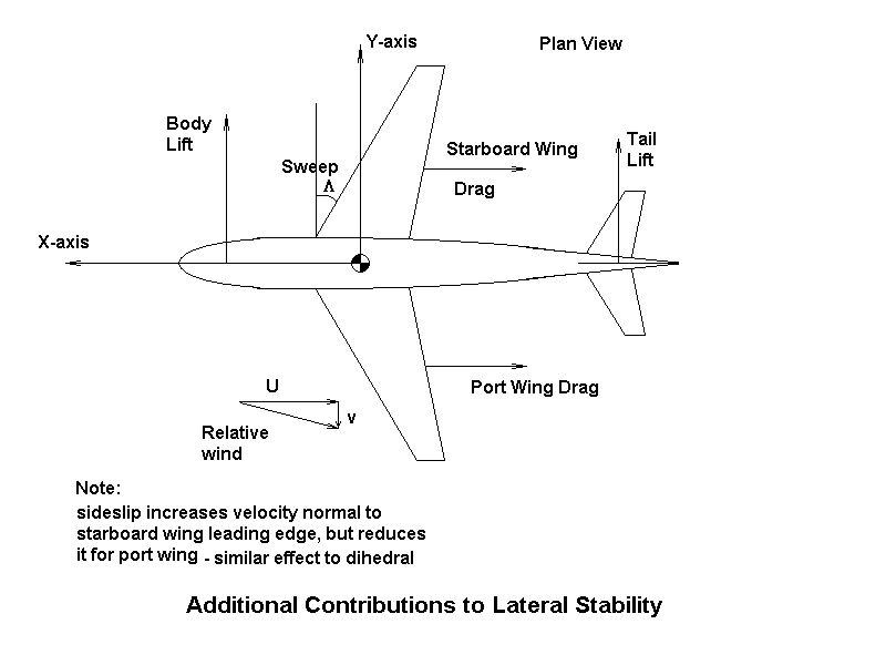
Sideslip generates a sideforce from the fin and the fuselage. In addition, if the wing has dihedral, side slip at a positive roll angle increases incidence on the starboard wing and reduces it on the port side, resulting in a net force component directly opposite to the sideslip direction. Sweep back of the wings has the same effect on incidence, but since the wings are not inclined in the vertical plane, backsweep alone does not affect Yβ. However, anhedral may be used with high backsweep angles in high performance aircraft to offset the wing incidence effects of sideslip. Oddly enough this does not reverse the sign of the wing configuration's contribution to Yβ (compared to the dihedral case).
Roll rate causes incidence at the fin, which generates a corresponding side force. Also, positive roll (starboard wing down) increases the lift on the starboard wing and reduces it on the port. If the wing has dihedral, this will result in a side force momentarily opposing the resultant sideslip tendency. Anhedral wing and or stabiliser configurations can cause the sign of the side force to invert if the fin effect is swamped.
Yawing generates side forces due to incidence at the rudder, fin and fuselage.
Sideslip in the absence of rudder input causes incidence on the fuselage and empennage, thus creating a yawing moment counteracted only by the directional stiffness which would tend to point the aircraft's nose back into the wind in horizontal flight conditions. Under sideslip conditions at a given roll angle Nβ will tend to point the nose into the sideslip direction even without rudder input, causing a downward spiralling flight.
Roll rate generates fin lift causing a yawing moment and also differentially alters the lift on the wings, thus affecting the induced drag contribution of each wing, causing a (small) yawing moment contribution. Positive roll generally causes positive Np values unless the empennage is anhedral or fin is below the roll axis. Lateral force components resulting from dihedral or anhedral wing lift differences has little effect on Np because the wing axis is normally closely aligned with the centre of gravity.
Yaw rate input at any roll angle generates rudder, fin and fuselage force vectors which dominate the resultant yawing moment. Yawing also increases the speed of the outboard wing whilst slowing down the inboard wing, with corresponding changes in drag causing a (small) opposing yaw moment. Nr opposes the inherent directional stiffness which tends to point the aircraft's nose back into the wind and always matches the sign of the yaw rate input.
A positive sideslip angle generates empennage incidence which can cause positive or negative roll moment depending on its configuration. For any non-zero sideslip angle dihedral wings causes a rolling moment which tends to return the aircraft to the horizontal, as does back swept wings. With highly swept wings the resultant rolling moment may be excessive for all stability requirements and anhedral could be used to offset the effect of wing sweep induced rolling moment.
Yaw increases the speed of the outboard wing whilst reducing speed of the inboard one, causing a rolling moment to the inboard side. The contribution of the fin normally supports this inward rolling effect unless offset by anhedral stabiliser above the roll axis (or dihedral below the roll axis).
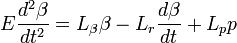
Roll creates counter rotational forces on both starboard and port wings whilst also generating such forces at the empennage. These opposing rolling moment effects have to be overcome by the aileron input in order to sustain the roll rate. If the roll is stopped at a non-zero roll angle the Lβ upward rolling moment induced by the ensueing sideslip should return the aircraft to the horizontal unless exceeded in turn by the downward Lr rolling moment resulting from sideslip induced yaw rate. Longitudinal stability could be ensured or improved by minimizing the latter effect. Equations of motionSince Dutch roll is a handling mode, analogous to the short period pitch oscillation, we shall ignore any effect it might have on the trajectory. The body rate r is made up of the rate of change of sideslip angle and the rate of turn. Taking the latter as zero, because we assume no effect on the trajectory, we have, for the limited purpose of studying the Dutch roll: The yaw and roll equations, with the stability derivatives become:
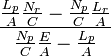
The inertial moment due to the roll acceleration is considered small compared with the aerodynamic terms, so the equations become: This becomes a second order equation governing either roll rate or sideslip: The equation for roll rate is identical. But the roll angle, φ (phi)is given by: If p is a damped simple harmonic motion, so is φ, but the roll must be in quadrature with the roll rate, and hence also with the sideslip. The motion consists of oscillations in roll and yaw, with the roll motion lagging 90 degrees behind the yaw. The wing tips trace out elliptical paths. Stability requires the 'stiffness' and 'damping' terms to be positive. These are:
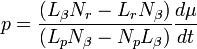
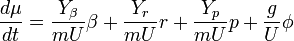
The denominator is dominated by Lp, the roll damping derivative, which is always negative, so the denominators of these two expressions will be positive. Considering the 'stiffness' term: − LpNβ will be positive because Lp is always negative and Nβ is positive by design. Lβ is usually negative, whilst Np is positive. Excessive dihedral can de-stabilise the Dutch roll, so configurations with highly swept wings require anhedral to offset the wing sweep contribution to Lβ. The damping term is dominated by the product of the roll damping and the yaw damping derivatives, these are both negative, so their product is positive. The Dutch roll should therefore be damped. The motion is accompanied by slight lateral motion of the centre of gravity and a more 'exact' analysis will introduce terms in Yβ etc. In view of the accuracy with which stability derivatives can be calculated, this is an unnecessary pedantry, which serves to obscure the relationship between aircraft geometry and handling, which is the fundamental objective of this article. Roll subsidenceJerking the stick sideways and returning it to centre causes a net change in roll orientation. The roll motion is characterized by an absence of natural stability, there are no stability derivatives which generate moments in response to the inertial roll angle. A roll disturbance induces a roll rate which is only cancelled by pilot or autopilot intervention. This takes place with insignificant changes in sideslip or yaw rate, so the equation of motion reduces to: Lp is negative, so the roll rate will decay with time. The roll rate reduces to zero, but there is no direct control over the roll angle. Spiral modeSimply holding the stick still, when starting with the wings near level, an aircraft will usually have a tendency to gradually veer off to one side of the straight flightpath. This is the (slightly unstable) spiral mode. The opposite holds for a stable spiral mode. The spiral mode is so-named because when it is slightly unstable, and the controls are not moved, the aircraft will tend to increase its bank angle slowly at first, then ever faster. The resulting path through the air is a continuously tightening and ever more rapidly descending spiral. An unstable spiral mode is common to most aircraft. It is not dangerous because the times to double the bank angle are large compared to the the pilot's ability to respond and correct errors with aileron inputs. When the spiral mode is stable, it behaves in a way opposite to the exponential divergence of the unstable mode. The stable spiral mode, when starting with the wings at a moderate bank angle, will return to near wings level, first quickly, then more slowly. When the spiral mode is stable and starting at a moderate bank angle, the spiral nature of the flight path is not as obvious. This is because usually only a fraction of a turn is made while the wings are not fully level. The turning starts out (relatively) tight, then becomes less and less so as the wings become more level. The divergence rate of the unstable spiral mode will be roughly proportional to the roll angle itself (i.e. roughly exponential growth). The convergence rate of the stable spiral mode will be roughly proportional to the roll angle itself (i.e. roughly exponential decay). Spiral mode trajectoryIn studying the trajectory, it is the direction of the velocity vector, rather than that of the body, which is of interest. The direction of the velocity vector when projected on to the horizontal will be called the track, denoted μ (mu). The body orientation is called the heading, denoted ψ (psi). The force equation of motion includes a component of weight: where g is the gravitational acceleration, and U is the speed. Including the stability derivatives: Roll rates and yaw rates are expected to be small, so the contributions of Yr and Yp will be ignored. The sideslip and roll rate vary gradually, so their time derivatives are ignored. The yaw and roll equations reduce to:
Solving for β and p: Substituting for sideslip and roll rate in the force equation results in a first order equation in roll angle: This is an exponential growth or decay, depending on whether the coefficient of φ is positive or negative. The denominator is usually negative, which requires LβNr > NβLr (both products are positive). This is in direct conflict with the Dutch roll stability requirement, and it is difficult to design an aircraft for which both the Dutch roll and spiral mode are inherently stable. Since the spiral mode has a long time constant, the pilot can intervene to effectively stabilise it, but an aircraft with an unstable Dutch roll would be difficult to fly. It is usual to design the aircraft with a stable Dutch roll mode, but slightly unstable spiral mode. See alsoFootnotesExternal links
Text from Wikipedia is available under the Creative Commons Attribution/Share-Alike License; additional terms may apply.
Published in July 2009. Click here to read more articles related to aviation and space!
|

 |
|
Copyright 2004-2026 © by Airports-Worldwide.com, Vyshenskoho st. 36, Lviv 79010, Ukraine Legal Disclaimer |


 is negligible over the period of the oscillation, so:

 , the pitch rate. The equations of motion, with all forces and moments referred to wind axes are, therefore:


 to be small compared with unity, so the coefficient of
 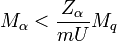 . This expression is dominated by
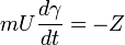


 (yaw)
(yaw)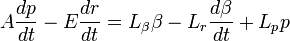 (roll)


 (damping)
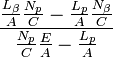 (stiffness)
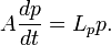

 (yaw)
(yaw) (roll)