 |
 |
|
||||
|
By
Wikipedia,
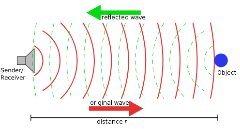
Radar is an object detection system that uses electromagnetic waves to identify the range, altitude, direction, or speed of both moving and fixed objects such as aircraft, ships, motor vehicles, weather formations, and terrain. The term RADAR was coined in 1941 as an acronym for radio detection and ranging. The term has since entered the English language as a standard word, radar, losing the capitalization. Radar was originally called RDF (Radio Direction Finder, now used as a totally different device) in the United Kingdom. A radar system has a transmitter that emits microwaves or radio waves. These waves are in phase when emitted, and when they come into contact with an object are scattered in all directions. The signal is thus partly reflected back and it has a slight change of wavelength (and thus frequency) if the target is moving. The receiver is usually, but not always, in the same location as the transmitter. Although the signal returned is usually very weak, the signal can be amplified through use of electronic techniques in the receiver and in the antenna configuration. This enables radar to detect objects at ranges where other emissions, such as sound or visible light, would be too weak to detect. Radar is used in meteorological detection of precipitation, measuring ocean surface waves, air traffic control, police detection of speeding traffic, and by the military. HistorySeveral inventors, scientists, and engineers contributed to the development of radar. The first to use radio waves to detect "the presence of distant metallic objects" was Christian Hülsmeyer, who in 1904 demonstrated the feasibility of detecting the presence of a ship in dense fog, but not its distance. He received Reichspatent Nr. 165546 for his pre-radar device in April 1904, and later patent 169154 for a related amendment for ranging. He also received a patent in England for his telemobiloscope on September 22, 1904. In August 1917 Nikola Tesla first established principles regarding frequency and power level for the first primitive radar units. He stated, "[...] by their [standing electromagnetic waves] use we may produce at will, from a sending station, an electrical effect in any particular region of the globe; [with which] we may determine the relative position or course of a moving object, such as a vessel at sea, the distance traversed by the same, or its speed." Before the Second World War developments by the Americans, the Germans, the French, the Soviets, and the British led to the modern version of radar. In 1934 the French Émile Girardeau stated he was building a radar system "conceived according to the principles stated by Tesla" and obtained a patent (French Patent n° 788795 in 1934) for a working dual radar system, a part of which was installed on the Normandie liner in 1935. The same year, American Dr. Robert M. Page tested the first monopulse radar and the Soviet military engineer P.K.Oschepkov, in collaboration with Leningrad Electrophysical Institute, produced an experimental apparatus RAPID capable of detecting an aircraft within 3 km of a receiver. Hungarian Zoltán Bay produced a working model by 1936 at the Tungsram laboratory in the same vein. However, it was the British who were the first to fully exploit it as a defence against aircraft attack. This was spurred on by fears that the Germans were developing death rays. Following a study of the possibility of propagating electromagnetic energy and the likely effect, the British scientists asked by the Air Ministry to investigate concluded that a death ray was impractical but detection of aircraft appeared feasible. Robert Watson-Watt demonstrated to his superiors the capabilities of a working prototype and patented the device in 1935 (British Patent GB593017) It served as the base for the Chain Home network of radars to defend Great Britain. The war precipitated research to find better resolution, more portability and more features for radar. The post-war years have seen the use of radar in fields as diverse as air traffic control, weather monitoring, astrometry and road speed control. PrinciplesThe radar dish, or antenna, transmits pulses of radio waves or microwaves which bounce off any object in their path. The object returns a tiny part of the wave's energy to a dish or antenna which is usually located at the same site as the transmitter. The time it takes for the reflected waves to return to the dish enables a computer to calculate how far away the object is, its radial velocity and other characteristics. Reflection
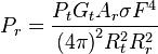
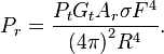
Electromagnetic waves reflect (scatter) from any large change in the dielectric or diamagnetic constants. This means that a solid object in air or a vacuum, or other significant change in atomic density between the object and what is surrounding it, will usually scatter radar (radio) waves. This is particularly true for electrically conductive materials, such as metal and carbon fiber, making radar particularly well suited to the detection of aircraft and ships. Radar absorbing material, containing resistive and sometimes magnetic substances, is used on military vehicles to reduce radar reflection. This is the radio equivalent of painting something a dark color. Radar waves scatter in a variety of ways depending on the size (wavelength) of the radio wave and the shape of the target. If the wavelength is much shorter than the target's size, the wave will bounce off in a way similar to the way light is reflected by a mirror. If the wavelength is much longer than the size of the target, the target is polarized (positive and negative charges are separated), like a dipole antenna. This is described by Rayleigh scattering, an effect that creates the Earth's blue sky and red sunsets. When the two length scales are comparable, there may be resonances. Early radars used very long wavelengths that were larger than the targets and received a vague signal, whereas some modern systems use shorter wavelengths (a few centimeters or shorter) that can image objects as small as a loaf of bread. Short radio waves reflect from curves and corners, in a way similar to glint from a rounded piece of glass. The most reflective targets for short wavelengths have 90° angles between the reflective surfaces. A structure consisting of three flat surfaces meeting at a single corner, like the corner on a box, will always reflect waves entering its opening directly back at the source. These so-called corner reflectors are commonly used as radar reflectors to make otherwise difficult-to-detect objects easier to detect, and are often found on boats in order to improve their detection in a rescue situation and to reduce collisions. For similar reasons, objects attempting to avoid detection will angle their surfaces in a way to eliminate inside corners and avoid surfaces and edges perpendicular to likely detection directions, which leads to "odd" looking stealth aircraft. These precautions do not completely eliminate reflection because of diffraction, especially at longer wavelengths. Half wavelength long wires or strips of conducting material, such as chaff, are very reflective but do not direct the scattered energy back toward the source. The extent to which an object reflects or scatters radio waves is called its radar cross section. Radar equationThe power Pr returning to the receiving antenna is given by the radar equation: where
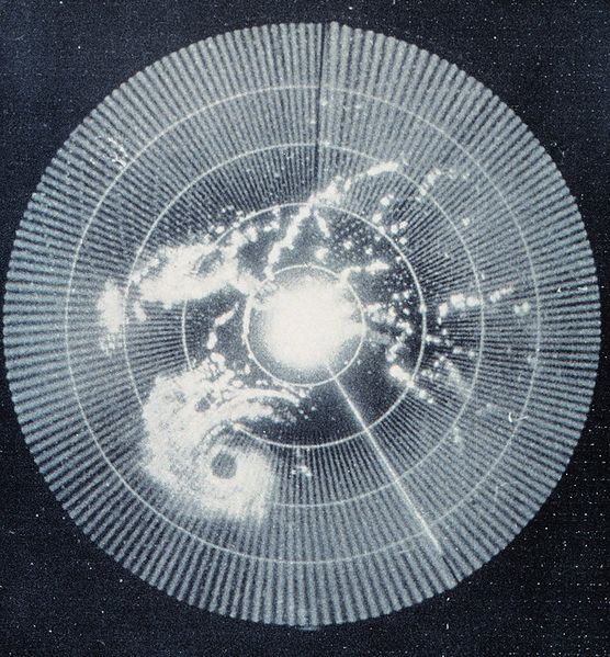
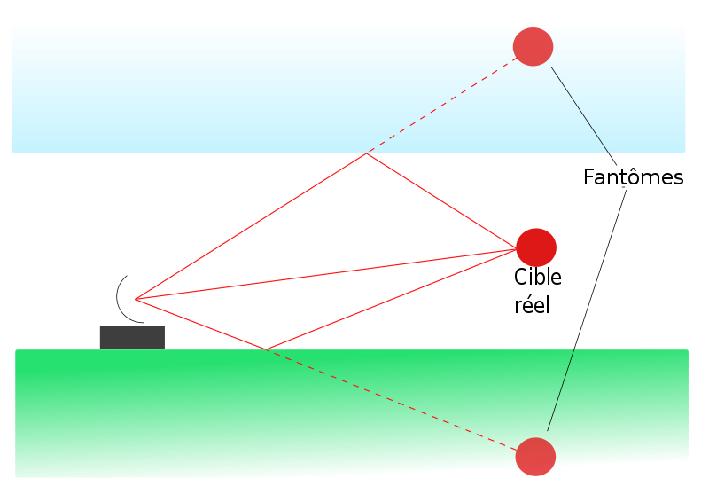
In the common case where the transmitter and the receiver are at the same location, Rt = Rr and the term Rt² Rr² can be replaced by R, where R is the range. This yields: This shows that the received power declines as the fourth power of the range, which means that the reflected power from distant targets is very, very small. The equation above with F = 1 is a simplification for vacuum without interference. The propagation factor accounts for the effects of multipath and shadowing and depends on the details of the environment. In a real-world situation, pathloss effects should also be considered. PolarizationIn the transmitted radar signal, the electric field is perpendicular to the direction of propagation, and this direction of the electric field is the polarization of the wave. Radars use horizontal, vertical, linear and circular polarization to detect different types of reflections. For example, circular polarization is used to minimize the interference caused by rain. Linear polarization returns usually indicate metal surfaces. Random polarization returns usually indicate a fractal surface, such as rocks or soil, and are used by navigation radars. InterferenceRadar systems must overcome unwanted signals in order to focus only on the actual targets of interest. These unwanted signals may originate from internal and external sources, both passive and active. The ability of the radar system to overcome these unwanted signals defines its signal-to-noise ratio (SNR). SNR is defined as the ratio of a signal power to the noise power within the desired signal. In less technical terms, SNR compares the level of a desired signal (such as targets) to the level of background noise. The higher a system's SNR, the better it is in isolating actual targets from the surrounding noise signals. NoiseSignal noise is an internal source of random variations in the signal, which is generated by all electronic components. Noise typically appears as random variations superimposed on the desired echo signal received in the radar receiver. The lower the power of the desired signal, the more difficult it is to discern it from the noise (similar to trying to hear a whisper while standing near a busy road). Noise figure is a measure of the noise produced by a receiver compared to an ideal receiver, and this needs to be minimized. Noise is also generated by external sources, most importantly the natural thermal radiation of the background scene surrounding the target of interest. In modern radar systems, due to the high performance of their receivers, the internal noise is typically about equal to or lower than the external scene noise. An exception is if the radar is aimed upwards at clear sky, where the scene is so "cold" that it generates very little thermal noise. There will be also flicker noise due to electrons transit, but depending on 1/f, will be much lower than thermal noise when the frequency is high. Hence, in pulse radar, the system will be always heterodyne. See intermediate frequency. ClutterClutter refers to radio frequency (RF) echoes returned from targets which are uninteresting to the radar operators. Such targets include natural objects such as ground, sea, precipitation (such as rain, snow or hail), sand storms, animals (especially birds), atmospheric turbulence, and other atmospheric effects, such as ionosphere reflections and meteor trails. Clutter may also be returned from man-made objects such as buildings and, intentionally, by radar countermeasures such as chaff. Some clutter may also be caused by a long radar waveguide between the radar transceiver and the antenna. In a typical plan position indicator (PPI) radar with a rotating antenna, this will usually be seen as a "sun" or "sunburst" in the centre of the display as the receiver responds to echoes from dust particles and misguided RF in the waveguide. Adjusting the timing between when the transmitter sends a pulse and when the receiver stage is enabled will generally reduce the sunburst without affecting the accuracy of the range, since most sunburst is caused by a diffused transmit pulse reflected before it leaves the antenna. While some clutter sources may be undesirable for some radar applications (such as storm clouds for air-defence radars), they may be desirable for others (meteorological radars in this example). Clutter is considered a passive interference source, since it only appears in response to radar signals sent by the radar. There are several methods of detecting and neutralizing clutter. Many of these methods rely on the fact that clutter tends to appear static between radar scans. Therefore, when comparing subsequent scans echoes, desirable targets will appear to move and all stationary echoes can be eliminated. Sea clutter can be reduced by using horizontal polarization, while rain is reduced with circular polarization (note that meteorological radars wish for the opposite effect, therefore using linear polarization the better to detect precipitation). Other methods attempt to increase the signal-to-clutter ratio. Constant False Alarm Rate (CFAR, a form of Automatic Gain Control, or AGC) is a method relying on the fact that clutter returns far outnumber echoes from targets of interest. The receiver's gain is automatically adjusted to maintain a constant level of overall visible clutter. While this does not help detect targets masked by stronger surrounding clutter, it does help to distinguish strong target sources. In the past, radar AGC was electronically controlled and affected the gain of the entire radar receiver. As radars evolved, AGC became computer-software controlled, and affected the gain with greater granularity, in specific detection cells. Clutter may also originate from multipath echoes from valid targets due to ground reflection, atmospheric ducting or ionospheric reflection/refraction. This clutter type is especially bothersome, since it appears to move and behave like other normal (point) targets of interest, thereby creating a ghost. In a typical scenario, an aircraft echo is multipath-reflected from the ground below, appearing to the receiver as an identical target below the correct one. The radar may try to unify the targets, reporting the target at an incorrect height, or - worse - eliminating it on the basis of jitter or a physical impossibility. These problems can be overcome by incorporating a ground map of the radar's surroundings and eliminating all echoes which appear to originate below ground or above a certain height. In newer Air Traffic Control (ATC) radar equipment, algorithms are used to identify the false targets by comparing the current pulse returns, to those adjacent, as well as calculating return improbabilities due to calculated height, distance, and radar timing. JammingRadar jamming refers to radio frequency signals originating from sources outside the radar, transmitting in the radar's frequency and thereby masking targets of interest. Jamming may be intentional, as with an electronic warfare (EW) tactic, or unintentional, as with friendly forces operating equipment that transmits using the same frequency range. Jamming is considered an active interference source, since it is initiated by elements outside the radar and in general unrelated to the radar signals. Jamming is problematic to radar since the jamming signal only needs to travel one-way (from the jammer to the radar receiver) whereas the radar echoes travel two-ways (radar-target-radar) and are therefore significantly reduced in power by the time they return to the radar receiver. Jammers therefore can be much less powerful than their jammed radars and still effectively mask targets along the line of sight from the jammer to the radar (Mainlobe Jamming). Jammers have an added effect of affecting radars along other lines of sight, due to the radar receiver's sidelobes (Sidelobe Jamming). Mainlobe jamming can generally only be reduced by narrowing the mainlobe solid angle, and can never fully be eliminated when directly facing a jammer which uses the same frequency and polarization as the radar. Sidelobe jamming can be overcome by reducing receiving sidelobes in the radar antenna design and by using an omnidirectional antenna to detect and disregard non-mainlobe signals. Other anti-jamming techniques are frequency hopping and polarization. See Electronic counter-counter-measures for details. Interference has recently become a problem for C-band (5.66 GHz) meteorological radars with the proliferation of 5.4 GHz band WiFi equipment. Radar signal processingDistance measurementTransit time
One way to measure the distance to an object is to transmit a short pulse of radio signal (electromagnetic radiation), and measure the time it takes for the reflection to return. The distance is one-half the product of round trip time (because the signal has to travel to the target and then back to the receiver) and the speed of the signal. Since radio waves travel at the speed of light (186,000 miles per second or 300,000,000 meters per second), accurate distance measurement requires high-performance electronics. In most cases, the receiver does not detect the return while the signal is being transmitted. Through the use of a device called a duplexer, the radar switches between transmitting and receiving at a predetermined rate. The minimum range is calculated by measuring the length of the pulse multiplied by the speed of light, divided by two. In order to detect closer targets one must use a shorter pulse length. A similar effect imposes a maximum range as well. If the return from the target comes in when the next pulse is being sent out, once again the receiver cannot tell the difference. In order to maximize range, longer times between pulses should be used, referred to as a pulse repetition time (PRT), or its reciprocal, pulse repetition frequency (PRF). These two effects tend to be at odds with each other, and it is not easy to combine both good short range and good long range in a single radar. This is because the short pulses needed for a good minimum range broadcast have less total energy, making the returns much smaller and the target harder to detect. This could be offset by using more pulses, but this would shorten the maximum range again. So each radar uses a particular type of signal. Long-range radars tend to use long pulses with long delays between them, and short range radars use smaller pulses with less time between them. This pattern of pulses and pauses is known as the pulse repetition frequency (or PRF), and is one of the main ways to characterize a radar. As electronics have improved many radars now can change their PRF thereby changing their range. The newest radars fire 2 pulses during one cell, one for short range 10 km / 6 miles and a separate signal for longer ranges 100 km /60 miles. The distance resolution and the characteristics of the received signal as compared to noise depends heavily on the shape of the pulse. The pulse is often modulated to achieve better performance using a technique known as pulse compression. Distance may also be measured as a function of time. The radar mile is the amount of time it takes for a radar pulse to travel one nautical mile, reflect off a target, and return to the radar antenna. Since a nautical mile is defined as exactly 1,852 meters, then dividing this distance by the speed of light (exactly 299,792,458 meters per second), and then multiplying the result by 2 (round trip = twice the distance), yields a result of approximately 12.36 microseconds in duration. Frequency modulationAnother form of distance measuring radar is based on frequency modulation. Frequency comparison between two signals is considerably more accurate, even with older electronics, than timing the signal. By changing the frequency of the returned signal and comparing that with the original, the difference can be easily measured. This technique can be used in continuous wave radar, and is often found in aircraft radar altimeters. In these systems a "carrier" radar signal is frequency modulated in a predictable way, typically varying up and down with a sine wave or sawtooth pattern at audio frequencies. The signal is then sent out from one antenna and received on another, typically located on the bottom of the aircraft, and the signal can be continuously compared using a simple beat frequency modulator that produces an audio frequency tone from the returned signal and a portion of the transmitted signal. Since the signal frequency is changing, by the time the signal returns to the aircraft the broadcast has shifted to some other frequency. The amount of that shift is greater over longer times, so greater frequency differences mean a longer distance, the exact amount being the "ramp speed" selected by the electronics. The amount of shift is therefore directly related to the distance traveled, and can be displayed on an instrument. This signal processing is similar to that used in speed detecting Doppler radar. Example systems using this approach are AZUSA, MISTRAM, and UDOP. A further advantage is that the radar can operate effectively at relatively low frequencies, comparable to that used by UHF television. This was important in the early development of this type when high frequency signal generation was difficult or expensive. A new terrestrial radar uses low-power FM signals that cover a larger frequency range. The multiple reflections are analyzed mathematically for pattern changes with multiple passes creating a computerized synthetic image. Doppler effects are not utilized which allows slow moving objects to be detected as well as largely eliminating "noise" from the surfaces of bodies of water. Used primarily for detection of intruders approaching in small boats or intruders crawling on the ground toward an objective. Speed measurementSpeed is the change in distance to an object with respect to time. Thus the existing system for measuring distance, combined with a memory capacity to see where the target last was, is enough to measure speed. At one time the memory consisted of a user making grease-pencil marks on the radar screen, and then calculating the speed using a slide rule. Modern radar systems perform the equivalent operation faster and more accurately using computers. However, if the transmitter's output is coherent (phase synchronized), there is another effect that can be used to make almost instant speed measurements (no memory is required), known as the Doppler effect. Most modern radar systems use this principle in the pulse-doppler radar system. Return signals from targets are shifted away from this base frequency via the Doppler effect enabling the calculation of the speed of the object relative to the radar. The Doppler effect is only able to determine the relative speed of the target along the line of sight from the radar to the target. Any component of target velocity perpendicular to the line of sight cannot be determined by using the Doppler effect alone, but it can be determined by tracking the target's azimuth over time. Additional information of the nature of the Doppler returns may be found in the radar signal characteristics article. It is also possible to make a radar without any pulsing, known as a continuous-wave radar (CW radar), by sending out a very pure signal of a known frequency. CW radar is ideal for determining the radial component of a target's velocity, but it cannot determine the target's range. CW radar is typically used by traffic enforcement to measure vehicle speed quickly and accurately where range is not important. Other mathematical developments in radar signal processing include time-frequency analysis (Weyl Heisenberg or wavelet), as well as the chirplet transform which makes use of the fact that radar returns from moving targets typically "chirp" (change their frequency as a function of time, as does the sound of a bird or bat). Reduction of interference effectsSignal processing is employed in radar systems to reduce the radar interference effects. Signal processing techniques include moving target indication (MTI), pulse doppler, moving target detection (MTD) processors, correlation with secondary surveillance radar (SSR) targets, space-time adaptive processing (STAP), and track-before-detect (TBD). Constant false alarm rate (CFAR) and digital terrain model (DTM) processing are also used in clutter environments. Plot And Track ExtractionRadar video returns on aircraft can be subjected to a plot extraction process whereby spurious and interfering signals are discarded. A sequence of target returns can be monitored through a device known as a plot extractor. The non relevant real time returns can be removed from the displayed information and a single plot displayed. In some radar systems, or alternatively in the command and control system to which the radar is connected, a radar tracker is used to associate the sequence of plots belonging to individual targets and estimate the targets' headings and speeds. Radar engineering
A radars components are:
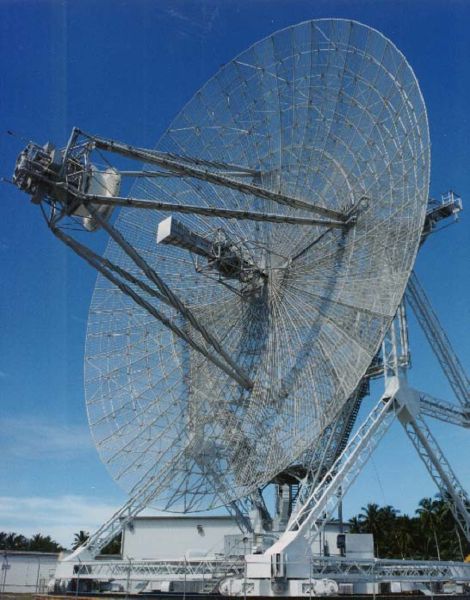
Antenna designRadio signals broadcast from a single antenna will spread out in all directions, and likewise a single antenna will receive signals equally from all directions. This leaves the radar with the problem of deciding where the target object is located. Early systems tended to use omni-directional broadcast antennas, with directional receiver antennas which were pointed in various directions. For instance the first system to be deployed, Chain Home, used two straight antennas at right angles for reception, each on a different display. The maximum return would be detected with an antenna at right angles to the target, and a minimum with the antenna pointed directly at it (end on). The operator could determine the direction to a target by rotating the antenna so one display showed a maximum while the other shows a minimum. One serious limitation with this type of solution is that the broadcast is sent out in all directions, so the amount of energy in the direction being examined is a small part of that transmitted. To get a reasonable amount of power on the "target", the transmitting aerial should also be directional. Parabolic reflectorMore modern systems use a steerable parabolic "dish" to create a tight broadcast beam, typically using the same dish as the receiver. Such systems often combine two radar frequencies in the same antenna in order to allow automatic steering, or radar lock. Parabolic reflectors can be either symmetric parabolas or spoiled parabolas:
Types of scan
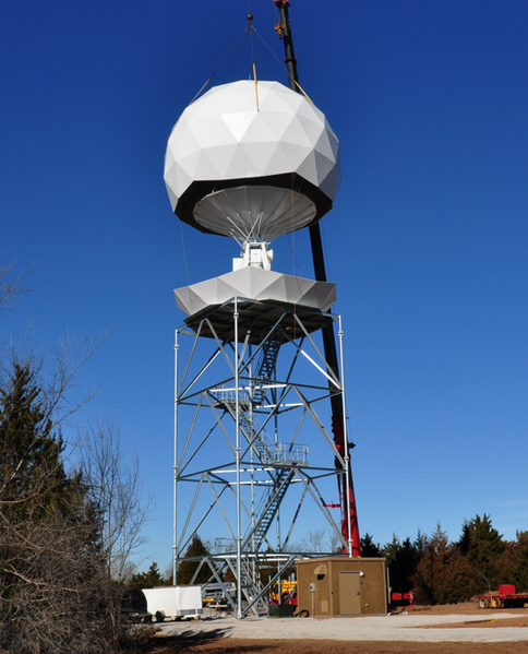
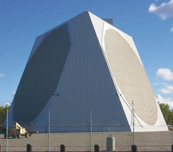
Slotted waveguideApplied similarly to the parabolic reflector, the slotted waveguide is moved mechanically to scan and is particularly suitable for non-tracking surface scan systems, where the vertical pattern may remain constant. Owing to its lower cost and less wind exposure, shipboard, airport surface, and harbour surveillance radars now use this in preference to the parabolic antenna. Phased arrayAnother method of steering is used in a phased array radar. This uses an array of similar aerials suitably spaced, the phase of the signal to each individual aerial being controlled so that the signal is reinforced in the desired direction and cancels in other directions. If the individual aerials are in one plane and the signal is fed to each aerial in phase with all others then the signal will reinforce in a direction perpendicular to that plane. By altering the relative phase of the signal fed to each aerial the direction of the beam can be moved because the direction of constructive interference will move. Because phased array radars require no physical movement the beam can scan at thousands of degrees per second, fast enough to irradiate and track many individual targets, and still run a wide-ranging search periodically. By simply turning some of the antennas on or off, the beam can be spread for searching, narrowed for tracking, or even split into two or more virtual radars. However, the beam cannot be effectively steered at small angles to the plane of the array, so for full coverage multiple arrays are required, typically disposed on the faces of a triangular pyramid (see picture). Phased array radars have been in use since the earliest years of radar use in World War II, but limitations of the electronics led to fairly poor accuracy. Phased array radars were originally used for missile defense. They are the heart of the ship-borne Aegis combat system, and the Patriot Missile System, and are increasingly used in other areas because the lack of moving parts makes them more reliable, and sometimes permits a much larger effective antenna, useful in fighter aircraft applications that offer only confined space for mechanical scanning. As the price of electronics has fallen, phased array radars have become more and more common. Almost all modern military radar systems are based on phased arrays, where the small additional cost is far offset by the improved reliability of a system with no moving parts. Traditional moving-antenna designs are still widely used in roles where cost is a significant factor such as air traffic surveillance, weather radars and similar systems. Phased array radars are also valued for use in aircraft, since they can track multiple targets. The first aircraft to use a phased array radar is the B-1B Lancer. The first aircraft fighter to use phased array radar was the Mikoyan MiG-31. The MiG-31M's SBI-16 Zaslon phased array radar is considered to be the world's most powerful fighter radar [2]. Phased-array interferometry or, aperture synthesis techniques, using an array of separate dishes that are phased into a single effective aperture, are not typically used for radar applications, although they are widely used in radio astronomy. Because of the Thinned array curse, such arrays of multiple apertures, when used in transmitters, result in narrow beams at the expense of reducing the total power transmitted to the target. In principle, such techniques used could increase the spatial resolution, but the lower power means that this is generally not effective. Aperture synthesis by post-processing of motion data from a single moving source, on the other hand, is widely used in space and airborne radar systems (see Synthetic aperture radar). Frequency bandsThe traditional band names originated as code-names during World War II and are still in military and aviation use throughout the world in the 21st century. They have been adopted in the United States by the IEEE, and internationally by the ITU. Most countries have additional regulations to control which parts of each band are available for civilian or military use. Other users of the radio spectrum, such as the broadcasting and electronic countermeasures (ECM) industries, have replaced the traditional military designations with their own systems.
Radar modulatorsModulators act to provide the short pulses of power to the magnetron, a special type of vacuum tube that converts DC (usually pulsed) into microwaves. This technology is known as Pulsed power. In this way, the transmitted pulse of RF radiation is kept to a defined, and usually, very short duration. Modulators consist of a high voltage pulse generator formed from an HV supply, a pulse forming network, and a high voltage switch such as a thyratron. A klystron tube may also be used as a modulator because it is an amplifier, so it can be modulated by its low power input signal. Radar coolantCoolanol and PAO (poly-alpha olefin) are the two main coolants used to cool airborne radar equipment today. The U.S. Navy has instituted a program named Pollution Prevention (P2) to reduce or eliminate the volume and toxicity of waste, air emissions, and effluent discharges. Because of this Coolanol is used less often today. PAO is a synthetic lubricant composition is a blend of a polyol ester admixed with effective amounts of an antioxidant, yellow metal pacifier and rust inhibitors. The polyol ester blend includes a major proportion of poly (neopentyl polyol) ester blend formed by reacting poly(pentaerythritol) partial esters with at least one C7 to C12 carboxylic acid mixed with an ester formed by reacting a polyol having at least two hydroxyl groups and at least one C8-C10 carboxylic acid. Preferably, the acids are linear and avoid those which can cause odours during use. Effective additives include secondary arylamine antioxidants, triazole derivative yellow metal pacifier and an amino acid derivative and substituted primary and secondary amine and/or diamine rust inhibitor. A synthetic coolant/lubricant composition, comprising an ester mixture of 50 to 80 weight percent of poly (neopentyl polyol) ester formed by reacting a poly (neopentyl polyol) partial ester and at least one linear monocarboxylic acid having from 6 to 12 carbon atoms, and 20 to 50 weight percent of a polyol ester formed by reacting a polyol having 5 to 8 carbon atoms and at least two hydroxyl groups with at least one linear monocarboxylic acid having from 7 to 12 carbon atoms, the weight percents based on the total weight of the composition. Radar configurations and typesRadars configurations include (Monopulse radar, Bistatic radar, Doppler radar, Continuous-wave radar, etc.. ) depending on the types of hardware and software used. It is used in aviation (Primary and secondary radar), sea vessels, law inforcement, weather surveillance, ground mapping, geophysical surveys, and biological research. See also
External links
Text from Wikipedia is available under the Creative Commons Attribution/Share-Alike License; additional terms may apply.
Published in July 2009. Click here to read more articles related to aviation and space!
|

 |
|
Copyright 2004-2026 © by Airports-Worldwide.com, Vyshenskoho st. 36, Lviv 79010, Ukraine Legal Disclaimer |