 |
 |
|
||||
|
By
Wikipedia,
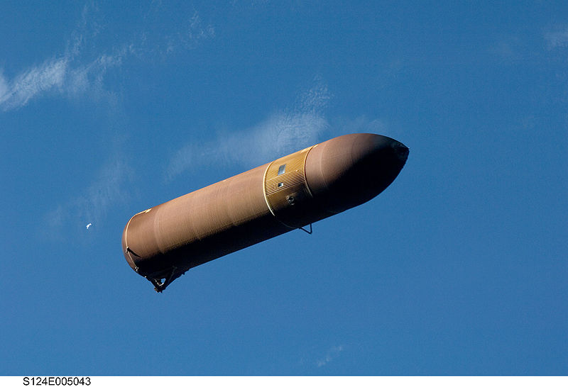
A Space Shuttle External Tank (ET) is the component of the Space Shuttle launch vehicle that contains the liquid hydrogen fuel and liquid oxygen oxidizer. During lift-off and ascent it supplies the fuel and oxidizer under pressure to the three space shuttle main engines (SSME) in the orbiter. The ET is jettisoned just over 10 seconds after MECO (Main Engine Cut Off), where the SSMEs are shut down, and re-enters the Earth's atmosphere. Unlike the Solid Rocket Boosters, external tanks are not reusable. They break up before impact in the Indian Ocean (or Pacific Ocean in the case of direct-insertion launch trajectories, which are currently utilized) away from known shipping lanes. Overview
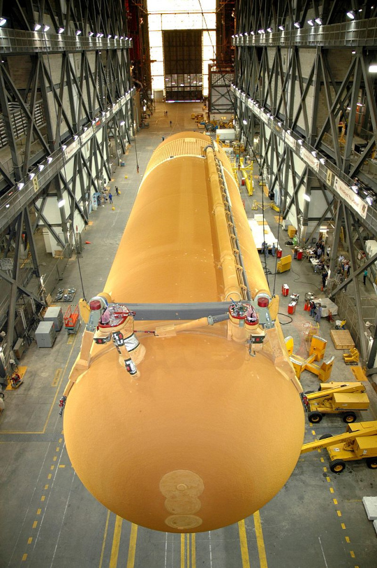
The ET is the largest element of the space shuttle, and when loaded, it is also the heaviest. It consists of three major components:
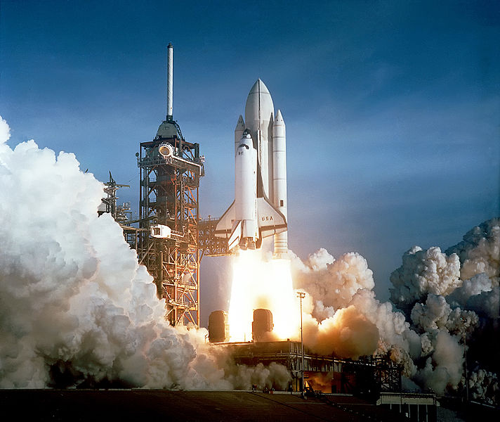
The ET is the "backbone" of the shuttle during launch, providing structural support for attachment with the solid rocket boosters (SRBs) and orbiter. The tank is connected to each SRB at one forward attachment point (using a crossbeam through the intertank) and one aft bracket, and it is connected to the orbiter at one forward attachment bipod and two aft bipods. In the aft attachment area, there are also umbilicals that carry fluids, gases, electrical signals and electrical power between the tank and the orbiter. Electrical signals and controls between the orbiter and the two solid rocket boosters also are routed through those umbilicals. Evolution of the ETStandard Weight TankThe original ET is informally known as the Standard Weight Tank (SWT). The first two, used in STS-1 and STS-2, were painted white to reduce solar heating and cryogenic boil off. Because this did not turn out to be a problem and to reduce weight, Lockheed Martin ceased painting the external tanks beginning with STS-3, leaving only the clear primer over the now-trademark rust-colored insulation, saving approximately 272 kg (600 lb) of weight. After STS-4, several hundred pounds were eliminated by deleting the anti-geyser line. This line paralleled the oxygen feed line, providing a circulation path for liquid oxygen. This reduces accumulation of gaseous oxygen in the feed line during prelaunch tanking (loading of the LOX). After propellant loading data from ground tests and the first few space shuttle missions was assessed, the anti-geyser line was removed for subsequent missions. The total length and diameter of the ET remain unchanged. The last SWT tank, flown on STS-7, weighed approximately 35,000 kg (77,000 lb) inert. Lightweight Tank
Beginning with the STS-6 mission, a lightweight ET (LWT), was introduced. This tank was used for the majority of the Shuttle flights, and was last used on the ill-fated STS-107 Space Shuttle Columbia flight. Although tanks vary slightly in weight, each weighed approximately 30,000 kg (66,000 lb) inert. The weight reduction from the SWT was accomplished by eliminating portions of stringers (structural stiffeners running the length of the hydrogen tank), using fewer stiffener rings and by modifying major frames in the hydrogen tank. Also, significant portions of the tank were milled differently to reduce thickness, and the weight of the ET's aft solid rocket booster attachments were reduced by using a stronger, yet lighter and less expensive titanium alloy. Super Lightweight TankThe Super Lightweight Tank (SLWT) was first flown in 1998 on STS-91 and has been used since with only two exceptions (STS-99 and STS-107). The SLWT is basically the same design as the LWT except that it uses an aluminum/lithium alloy (Al 2195) for a large part of the tank structure. This alloy provides a significant reduction in tank weight (~3,175 kg/7,000 lb) over the LWT. The disadvantages of the SLWT are its increased cost (~$5 million) and production time (~4 months) when compared to the LWT. Although all ETs currently produced are of the SLWT configuration, one LWT remains in inventory and can be used if requested. The SLWT provides 50% of the performance increase required for the shuttle to reach the international space station.
Technical dataSLWT Specifications
LOX tank
Intertank
LH2 tank
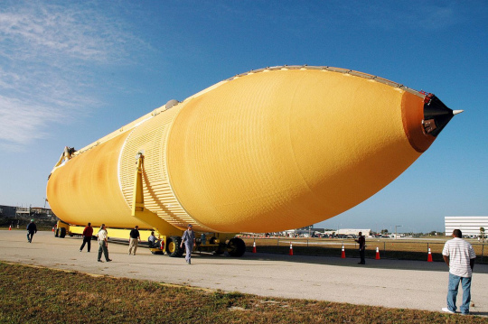
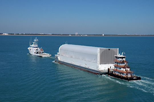
ContractorThe contractor for the external tank is Lockheed Martin (previously Martin Marietta), New Orleans, Louisiana. The tank is manufactured at the Michoud Assembly Facility, New Orleans, and is transported to Kennedy Space Center by barge. ComponentsThe ET has three primary structures: an LOX tank, an intertank, and an LH2 tank. Both tanks are constructed of aluminum alloy skins with support or stability frames as required. The intertank aluminum structure utilizes skin stringers with stabilizing frames. The primary aluminum materials used for all three structures are 2195 and 2090 alloys. AL 2195 is an Al-Li alloy designed by Lockheed Martin and Reynolds for storage of cryogenics. Al 2090 is a commercially available Al-Li alloy. Liquid oxygen tankThe LOX tank is located at the top of the ET and has an ogive shape to reduce aerodynamic drag and aerothermodynamic heating. The ogive nose section is capped by a flat removable cover plate and a nose cone. The nose cone consists of a removable conical assembly that serves as an aerodynamic fairing for the propulsion and electrical system components. The forward most element of the nose cone functions as a cast aluminum lightning rod. The LOX tank volume is 19,744 cu ft (559.1 m) at 22 psig (250 kPa absolute) and −297 °F (90.4 K; −182.8 °C) (cryogenic). The tank feeds into a 17 in (430 mm) diameter feed line that conveys the liquid oxygen through the intertank, then outside the ET to the aft right-hand ET/orbiter disconnect umbilical. The 17 in (430 mm) diameter feed line permits liquid oxygen to flow at approximately 2,787 lb/s (1264 kg/s) with the SSMEs operating at 104 % or permits a maximum flow of 17,592 gal/min (1.1099 m³/s). All loads except aerodynamic loads are transferred from the LOX tank at a bolted, flange-joint interface with the intertank. The LOX tank also includes an internal slosh baffle and a vortex baffle to dampen fluid slosh. The vortex baffle is mounted over the LOX feed outlet to reduce fluid swirl resulting from slosh and to prevent entrapment of gases in the delivered LOX. IntertankThe intertank is the ET structural connection which joins both the LOX and LH2 tanks. Its primary functions are to receive and distribute all thrust loads from the SRBs and transfer loads between the tanks. The SRB two forward attach fittings are located 180° apart on the intertank structure. A beam is extended across the intertank structure and is mechanically fastened to the attach fittings. When the SRBs are firing, the beam will flex due to high stress loads. These loads will be transferred to the fittings. Adjoining the SRB attach fittings is a major ring frame. The loads are transferred from the fittings to the major ring frame which then distributes the tangential loads to the intertank skin. Two panels of the intertank skin, called the thrust panels, distribute the concentrated axial SRB thrust loads to the LOX and LH2 tanks and to adjacent intertank skin panels. These adjacent panels are made up of six stringer-stiffened panels. The intertank also functions as a protective compartment for housing the operational instrumentation. Liquid hydrogen tank
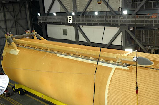
The LH2 tank is the bottom portion of the ET. The tank is constructed of four cylindrical barrel sections, a forward dome, and an aft dome. The barrel sections are joined together by five major ring frames. These ring frames receive and distribute loads. The forward dome-to-barrel frame distributes the loads applied through the intertank structure and is also the flange for attaching the LH2 tank to the intertank. The aft major ring receives orbiter-induced loads from the aft orbiter support struts and SRB-induced loads from the aft SRB support struts. The remaining three ring frames distribute orbiter thrust loads and LOX feedline support loads. Loads from the frames are then distributed through the barrel skin panels. The LH2 tank has a volume of 53,488 cubic feet (1,514.6 m) at 29.3 psig (3.02 bar absolute) and −423 °F (20.4 K; −252.8 °C) (cryogenic). The forward and aft domes have the same modified ellipsoidal shape. For the forward dome, mounting provisions are incorporated for the LH2 vent valve, the LH2 pressurization line fitting, and the electrical feed-through fitting. The aft dome has a manhole fitting for access to the LH2 feedline screen and a support fitting for the LH2 feedline. The LH2 tank also has a vortex baffle to reduce swirl resulting from slosh and to prevent entrapment of gases in the delivered LH2. The baffle is located at the siphon outlet just above the aft dome of the LH2 tank. This outlet transmits the liquid hydrogen from the tank through a 17 inches (430 mm) line to the left aft umbilical. The liquid hydrogen feed line flow rate is 465 lb/s (211 kg/s) with the SSMEs at 104% or a maximum flow of 47,365 US gal/min (2.988 m³/s). ET thermal protection system
The ET thermal protection system consists primarily of sprayed-on foam insulation, plus preformed foam pieces and premolded ablator materials. The system also includes the use of phenolic thermal insulators to preclude air liquefaction. Thermal isolators are required for liquid hydrogen tank attachments to preclude the liquefaction of air on exposed metal, and to reduce heat flow into the liquid hydrogen. While the warmer liquid oxygen results in fewer thermal requirements, the aluminum of the liquid oxygen tank forward areas require protection from aeroheating. Meanwhile insulation on the aft surfaces prevents liquified air from pooling in the intertank. The middle cylinder of the oxygen tank, and the propellant lines, could withstand the expected depths of frost accumulation condensed from humidity, but the orbiter could not take the damage from ice breaking free. The thermal protection system weighs 4,823 lb (2,188 kg). Development of the ETs thermal protection system has been problematic. Anomalies in foam application were so frequent that they were treated as variances, not safety incidents. NASA has had difficulty preventing fragments of foam from detaching during flight for the entire history of the program:
In 1995, chlorofluorocarbon-11 (CFC-11) began to be withdrawn from large-area, machine-sprayed foams in compliance with an Environmental Protection Agency ban on CFCs under section 610 of the Clean Air Act. In its place, a hydrochlorofluorocarbon known as HCFC 141b was certified for use and phased into the shuttle program. Remaining foams, particularly detail pieces sprayed by hand, continue to use CFC-11 to this day. These areas include the problematic bipod and PAL ramps, as well as some fittings and interfaces. For the bipod ramp in particular, "the process of applying foam to that part of the tank had not changed since 1993." The "new" foam containing HCFC 141b was first used on the aft dome portion of ET-82 during the flight of STS-79 in 1996. Use of HCFC 141b was expanded to the ETs area, or larger portions of the tank, starting with ET-88, which flew on STS-86 in 1997. During the lift-off of STS-107, a piece of foam insulation detached from one of the tank's bipod ramps and struck the leading edge of Space Shuttle Columbia's wing at a few hundred miles per hour. The impact is believed to have damaged several reinforced carbon-carbon thermal tiles on the leading edge of the wing, which allowed super-heated gas to enter the wing superstructure several days later during re-entry. This resulted in the destruction of Columbia and the loss of its crew. In 2005, the problem of foam shed had not been fully cured; on STS-114, additional cameras mounted on the tank recorded a piece of foam separated from one of its Protuberance Air Load (PAL) ramps, which are designed to prevent unsteady air flow underneath the tank’s cable trays and pressurization lines during ascent. The PAL ramps consist of manually sprayed layers of foam, and are more likely to become a source of debris. That piece of foam did not impact the orbiter. Reports published concurrent with the STS-114 mission suggest that excessive handling of the ET during modification and upgrade may have contributed to the foam loss on Discovery's Return to Flight mission. However, three shuttle missions (STS-121,STS-115, and STS-116) have since been conducted, all with "acceptable" levels of foam loss. However on STS-118 a piece of foam (and/or ice) about 10 cm in diameter separated from a feedline attachment bracket on the tank, ricocheted off one of the aft struts and struck the underside of the wing, damaging two tiles. The damage was not considered dangerous. ET hardwareThe external hardware, ET / orbiter attachment fittings, umbilical fittings, electrical and range safety system weigh 9,100 lb (4.1 t). Each propellant tank has a vent and relief valve at its forward end. This dual-function valve can be opened by ground support equipment for the vent function during prelaunch and can open during flight when the ullage (empty space) pressure of the liquid hydrogen tank reaches 38 psig (360 kPa absolute) or the ullage pressure of the liquid oxygen tank reaches 25 psig (270 kPa absolute). The liquid oxygen tank contains a separate, pyrotechnically operated, propulsive tumble vent valve at its forward end. At separation, the liquid oxygen tumble vent valve is opened, providing impulse to assist in the separation maneuver and more positive control of the entry aerodynamics of the ET.
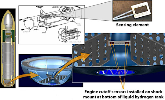
There are eight propellant-depletion sensors, four each for fuel and oxidizer. The fuel-depletion sensors are located in the bottom of the fuel tank. The oxidizer sensors are mounted in the orbiter liquid oxygen feed line manifold downstream of the feed line disconnect. During SSME thrusting, the orbiter general-purpose computers constantly compute the instantaneous mass of the vehicle due to the usage of the propellants. Normally, main engine cutoff is based on a predetermined velocity; however, if any two of the fuel or oxidizer sensors sense a dry condition, the engines will be shut down. The locations of the liquid oxygen sensors allow the maximum amount of oxidizer to be consumed in the engines, while allowing sufficient time to shut down the engines before the oxidizer pumps cavitate (run dry). In addition, 1,100 lb (500 kg) of liquid hydrogen are loaded over and above that required by the 6-1 oxidizer / fuel engine mixture ratio. This assures that cutoff from the depletion sensors is fuel-rich; oxidizer-rich engine shutdowns can cause burning and severe erosion of engine components, potentially leading to loss of the vehicle and crew. Unexplained, erroneous readings from fuel depletion sensors have delayed several shuttle launch attempts, most notably STS-122. On 2007-12-18 a tanking test determined the cause of the errors to be a fault in a wiring connector, rather than a failure of the sensors themselves. Four pressure transducers located at the top of the liquid oxygen and liquid hydrogen tanks monitor the ullage pressures.
Each of the two aft external tank umbilical plates mate with a corresponding plate on the orbiter. The plates help maintain alignment among the umbilicals. Physical strength at the umbilical plates is provided by bolting corresponding umbilical plates together. When the orbiter GPCs command external tank separation, the bolts are severed by pyrotechnic devices. The ET has five propellant umbilical valves that interface with orbiter umbilicals: two for the liquid oxygen tank and three for the liquid hydrogen tank. One of the liquid oxygen tank umbilical valves is for liquid oxygen, the other for gaseous oxygen. The liquid hydrogen tank umbilical has two valves for liquid and one for gas. The intermediate-diameter liquid hydrogen umbilical is a recirculation umbilical used only during the liquid hydrogen chill-down sequence during prelaunch. The ET also has two electrical umbilicals that carry electrical power from the orbiter to the tank and the two SRBs and provide information from the SRBs and ET to the orbiter. A swing-arm-mounted cap to the fixed service structure covers the oxygen tank vent on top of the ET during the countdown and is retracted about two minutes before lift- off. The cap siphons off oxygen vapor that threatens to form large ice on the ET, thus protecting the orbiter's thermal protection system during launch. The ET has external cameras mounted in the brackets which attached to the shuttle along with transmitters that can continue to send video data long after the shuttle and the ET have separated. ET range safety systemEarlier tanks incorporated a range safety system to disperse tank propellants if necessary. It included a battery power source, a receiver/decoder, antennas and ordnance. Starting with STS-79, this system was no longer used. The assembly was completely removed by the time STS-88 flew and has not been present on any tank since then. Consequently, it is no longer possible to destroy the vehicle during second stage ascent. VariantsA cargo carrier addition was studied in 1984. This would consist of a cargo space mounted to the aft hydrogen dome, for cargoes greater than the payload bay diameter of 15 feet (4.6 m). It never flew. Before the Challenger accident, proposed west coast launches by the military into polar orbits suffered a disadvantage in lifting capacity compared to low-inclination orbits. A booster module, derived from a Titan II first stage, was proposed. In addition to increasing capacity, the presence of tankage and rocket exhaust would have relieved heating on the aft hydrogen dome. This also failed to fly. Future useWith the planned retirement of the Space Shuttle by 2011, NASA, with its planned Project Constellation, which features the Apollo-derived Orion spacecraft, will also feature the debut of two Shuttle-derived launch vehicles, the man-rated Ares I crew-launch vehicle and the heavy-lift Ares V cargo-launch vehicle. While both the Ares I and Ares V will utilize a modified five-segment Solid Rocket Booster for its first stage, the current ET will serve as a baseline technology for the first stage of the Ares V and the second stage of the Ares I; as a comparison, the Ares I second stage will hold approximately 26,000 US gal (98,000 l) of LOX, versus the ET holding 146,000 US gal (550,000 l), more than 5 times that amount. The Ares V first stage, which will be fitted with five RS-68 rocket engines (the same engine used on the Delta IV rocket), will be 33 feet (10 m) in diameter, as wide as the S-IC and S-II stages on the Saturn V rocket. It will utilize the same internal ET configuration (separate LH2 and LOX tanks separated with an intertank structure), but will be configured to directly accept LH2 and LOX fill and drain, along with LOX venting on a retractable arm like that used on the Shuttle for LH2 (as the "beanie cap" would be useless due to the in-line design of the three-stage vehicle).
The Ares I second stage, on the other hand, will only use the spray-on insulation foam currently used on the current ET. Originally configured like that of the Ares V and the Shuttle ET, NASA, upon completing its design review in 2006, decided, in order to save weight and costs, to reconfigure the internal structure of the second stage by using a combined LH2/LOX tank with the propellants separated by a common bulkhead, a configuration successfully used on the S-II and S-IVB stages of the Saturn V rocket. Unlike the Ares V, which will use the same fill/drain/vent configuration used on the Shuttle, the Ares I system will utilize a traditional fill/drain/vent system used on the Saturn IB and Saturn V rockets, but with quick-retracting arms due to the "leap frog" speed the Ares I will expect upon SRB ignition. As originally envisioned, both the Ares I and Ares V would have used a modified "throw away" version of the SSME, but in due course, because of the need to keep R&D costs down and to maintain a schedule set by NASA Administration Michael D. Griffin to launch the Ares and Orion by 2011, NASA decided to switch to the RS-68 engine for the Ares V and to an uprated J-2 engine for the Ares I. Because of the switch to the RS-68, the Ares V was widened from 28.6 to 33 feet (8.72 to 10.06 m) to accommodate the extra propellants, while the Ares I was reconfigured to incorporate a fifth solid-rocket segment as the J-2X, as the rocket engine is known, has less thrust than the SSME. Because of the trade-off, NASA would save an estimated USD $35 million by using simplified, higher thrust RS-68 engines (by reconfigured to fire and perform like the SSME), while at the same time, eliminate the costly tests needed for an air-startable SSME for the Ares I (as the J-2X and its predecessor was designed to be started in both mid-air and in a near vacuum). The DIRECT project, a proposed alternative shuttle-derived vehicle, uses a modified, standard diameter, external tank with two RS-68 engines, with two standard SRBM, as a Crew Launch Vehicle. The same vehicle, with one extra RS-68 engine, and an EDS upper stage, serves as the Cargo Launch Vehicle. It is purported to save $16 billion, eliminate NASA job losses, and reduce the post-shuttle, manned spaceflight gap from five plus years to two or less. See alsoExternal links
Text from Wikipedia is available under the Creative Commons Attribution/Share-Alike License; additional terms may apply.
Published in July 2009. Click here to read more articles related to aviation and space!
|

 |
|
Copyright 2004-2026 © by Airports-Worldwide.com, Vyshenskoho st. 36, Lviv 79010, Ukraine Legal Disclaimer |
.jpg)
