 |
 |
|
||||
|
By
Wikipedia, In fluid dynamics, drag (sometimes called air resistance or fluid resistance) refers to forces that oppose the relative motion of an object through a fluid (a liquid or gas). Drag forces act in a direction opposite to the oncoming flow velocity. Unlike other resistive forces such as dry friction, which is nearly independent of velocity, drag forces depend on velocity. For a solid object moving through a fluid, the drag is the component of the net aerodynamic or hydrodynamic force acting opposite to the direction of the movement. The component perpendicular to this direction is considered lift. Therefore drag opposes the motion of the object, and in a powered vehicle it is overcome by thrust. In astrodynamics, depending on the situation, atmospheric drag can be regarded as an inefficiency requiring expense of additional energy during launch of the space object or as a bonus simplifying return from orbit. Types of dragTypes of drag are generally divided into the following categories:
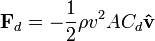
The phrase parasitic drag is mainly used in aerodynamics, since for lifting wings drag is in general small compared to lift. For flow around bluff bodies, drag is most often dominating, and then the qualifier "parasitic" is meaningless. Form drag, skin friction and interference drag on bluff bodies are not coined as being elements of parasitic drag, but directly as elements of drag. For high velocities — or more precisely, at high Reynolds numbers — the overall drag of an object is characterized by a dimensionless number called the drag coefficient, and is calculated using the drag equation. Assuming a more-or-less constant drag coefficient, drag will vary as the square of velocity. Thus, the resultant power needed to overcome this drag will vary as the cube of velocity. The standard equation for drag is one half the coefficient of drag multiplied by the fluid mass density, the cross sectional area of the specified item, and the square of the velocity. Wind resistance is a layman's term used to describe drag. Its use is often vague, and is usually used in a relative sense (e.g., a badminton shuttlecock has more wind resistance than a squash ball). Drag at high velocityExplanation of drag by NASA.The drag equation calculates the force experienced by an object moving through a fluid at relatively large velocity (i.e. high Reynolds number, Re > ~1000), also called quadratic drag. The equation is attributed to Lord Rayleigh, who originally used L in place of A (L being some length). The force on a moving object due to a fluid is: where
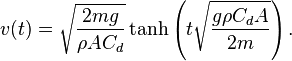
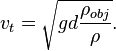
The reference area A is often defined as the area of the orthographic projection of the object — on a plane perpendicular to the direction of motion — e.g. for objects with a simple shape, such as a sphere, this is the cross sectional area. Sometimes different reference areas are given for the same object in which case a drag coefficient corresponding to each of these different areas must be given. In case of a wing, comparison of the drag to the lift force is easiest when the reference areas are the same, since then the ratio of drag to lift force is just the ratio of drag to lift coefficient. Therefore, the reference for a wing often is the planform (or wing) area rather than the frontal area. For an object with a smooth surface, and non-fixed separation points — like a sphere or circular cylinder — the drag coefficient may vary with Reynolds number Re, even up to very high values (Re of the order 10).For an object with well-defined fixed separation points, like a circular disk with its plane normal to the flow direction, the drag coefficient is constant for Re > 3,500. Further the drag coefficient Cd is, in general, a function of the orientation of the flow with respect to the object (apart from symmetrical objects like a sphere). PowerThe power required to overcome the aerodynamic drag is given by: Note that the power needed to push an object through a fluid increases as the cube of the velocity. A car cruising on a highway at 50 mph (80 km/h) may require only 10 horsepower (7.5 kW) to overcome air drag, but that same car at 100 mph (160 km/h) requires 80 hp (60 kW). With a doubling of speed the drag (force) quadruples per the formula. Exerting four times the force over a fixed distance produces four times as much work. At twice the speed the work (resulting in displacement over a fixed distance) is done twice as fast. Since power is the rate of doing work, four times the work done in half the time requires eight times the power. Velocity of a falling objectThe velocity as a function of time for an object falling through a non-dense medium, and released at zero relative-velocity v = 0 at time t = 0, is roughly given by a function involving a hyperbolic tangent (tanh): The hyperbolic tangent has a limit value of one, for large time t. In other words, velocity asymptotically approaches a maximum value called the terminal velocity vt: For a potato-shaped object of average diameter d and of density ρobj, terminal velocity is about For objects of water-like density (raindrops, hail, live objects — animals, birds, insects, etc.) falling in air near the surface of the Earth at sea level, terminal velocity is roughly equal to with d in metre and vt in m/s. For example, for a human body ( Terminal velocity is higher for larger creatures, and thus potentially more deadly. A creature such as a mouse falling at its terminal velocity is much more likely to survive impact with the ground than a human falling at its terminal velocity. A small animal such as a cricket impacting at its terminal velocity will probably be unharmed. This explains why small animals can fall from a large height and not be harmed. Very low Reynolds numbers — Stokes' drag
The equation for viscous resistance or linear drag is appropriate for objects or particles moving through a fluid at relatively slow speeds where there is no turbulence (i.e. low Reynolds number, Re < 1). In this case, the force of drag is approximately proportional to velocity, but opposite in direction. The equation for viscous resistance is: where:
When an object falls from rest, its velocity will be which asymptotically approaches the terminal velocity For the special case of small spherical objects moving slowly through a viscous fluid (and thus at small Reynolds number), George Gabriel Stokes derived an expression for the drag constant, where:
For example, consider a small sphere with radius Drag in aerodynamicsParasitic dragParasitic drag (also called parasite drag) is drag caused by moving a solid object through a fluid. Parasitic drag is made up of multiple components including viscous pressure drag (form drag), and drag due to surface roughness (skin friction drag). Additionally, the presence of multiple bodies in relative proximity may incur so called interference drag, which is sometimes described as a component of parasitic drag. In aviation, induced drag tends to be greater at lower speeds because a high angle of attack is required to maintain lift, creating more drag. However, as speed increases the induced drag becomes much less, but parasitic drag increases because the fluid is flowing faster around protruding objects increasing friction or drag. At even higher speeds in the transonic, wave drag enters the picture. Each of these forms of drag changes in proportion to the others based on speed. The combined overall drag curve therefore shows a minimum at some airspeed - an aircraft flying at this speed will be at or close to its optimal efficiency. Pilots will use this speed to maximize endurance (minimum fuel consumption), or maximise gliding range in the event of an engine failure. Lift induced dragLift-induced drag (also called induced drag) is drag which occurs as the result of the creation of lift on a three-dimensional lifting body, such as the wing or fuselage of an airplane. Induced drag consists of two primary components, including drag due to the creation of vortices (vortex drag) and the presence of additional viscous drag (lift-induced viscous drag). The vortices in the flow-field, present in the wake of a lifting body, derive from the turbulent mixing of air of varying pressure on the upper and lower surfaces of the body, which is a necessary condition for the creation of lift. With other parameters remaining the same, as the lift generated by a body increases, so does the lift-induced drag. For an aircraft in flight, this means that as the angle of attack, and therefore the lift, of the lifting body increases to the point of stall, so does the lift-induced drag. At the onset of stall, lift is abruptly decreased, as is lift-induced drag, but viscous pressure drag, a component of parasite drag, increases due to the formation of turbulent unattached flow on the surface of the body. Wave drag in transonic and supersonic flowWave drag (also called compressibility drag) is drag which is created by the presence of a body moving at high speed through a compressible fluid. In aerodynamics, Wave drag consists of multiple components depending on the speed regime of the flight. In transonic flight (Mach numbers greater than 0.5 and less than 1.0), wave drag is the result of the formation of shockwaves on the body, formed when areas of local supersonic (Mach number greater than 1.0) flow are created. In practice, supersonic flow occurs on bodies traveling well below the speed of sound, as the local speed of air on a body increases when it accelerates over the body, in this case above Mach 1.0. Therefore, aircraft flying at transonic speed often incur wave drag through the normal course of operation. In transonic flight, wave drag is commonly referred to as transonic compressibility drag. Transonic compressibility drag increases significantly as the speed of flight increases towards Mach 1.0, dominating other forms of drag at these speeds. In supersonic flight (Mach numbers greater than 1.0), wave drag is the result of shockwaves present on the body, typically oblique shockwaves formed at the leading and trailing edges of the body. In highly supersonic flows, or in bodies with turning angles sufficiently large, unattached shockwaves, or bow waves will instead form. Additionally, local areas of transonic flow behind the initial shockwave may occur at lower supersonic speeds, and can lead to the development of additional, smaller shockwaves present on the surfaces of other lifting bodies, similar to those found in transonic flows. In supersonic flow regimes, wave drag is commonly separated into two components, supersonic lift-dependent wave drag and supersonic volume-dependent wave drag. A closed form solution for the minimum wave drag of a body of revolution with a fixed length was found by Sears and Haack, and is known as the Sears-Haack Distribution. Similarly, for a fixed volume, the shape for minimum wave drag is the Von Karman Ogive. Busemann's Biplane is not, in principle, subject to wave drag at all when operated at its design speed, but is incapable of generating lift. d'Alembert's paradoxIn 1752 d'Alembert proved that potential flow, the 18 century state-of-the-art inviscid flow theory amenable to mathematical solutions, resulted in the prediction of zero drag. This was in contradiction with experimental evidence, and became known as d'Alembert's paradox. In the 19 century the Navier–Stokes equations for the description of viscous flow were developed by Saint-Venant, Navier and Stokes. And for the flow around a sphere at very low Reynolds numbers, Stokes was able to derive the drag — called Stokes law. However, in the limit of high-Reynolds numbers the Navier–Stokes equations approach the inviscid Euler equations; of which the potential-flow solutions considered by d'Alembert are solutions. While also at high Reynolds numbers all experiments showed there is drag. Attempts to construct inviscid steady flow solutions to the Euler equations, other than the potential flow solutions, did not result in realistic results. The notion of boundary layers — introduced by Prandtl in 1904, founded on both theory and experiments — explained the causes of drag at high Reynolds numbers. The boundary layer is the thin layer of fluid close to the object's boundary, where viscous effects remain important when the viscosity becomes very small (or equivalently the Reynolds number becomes very large). See also
External links
Text from Wikipedia is available under the Creative Commons Attribution/Share-Alike License; additional terms may apply.
Published in July 2009. Click here to read more articles related to aviation and space!
|

 |
|
Copyright 2004-2026 © by Airports-Worldwide.com, Vyshenskoho st. 36, Lviv 79010, Ukraine Legal Disclaimer |
 is the
  is the
  is the
  is the reference
  is the
  is the
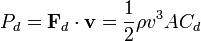


 ~ 0.6 m)
  ~ 70 m/s, for a small animal like a cat (

 is a constant that depends on the properties of the fluid and the dimensions of the object, and
 is the velocity of the object.
 . For a given
 is the
  is the fluid viscosity.