 |
 |
|
||||
|
By
Wikipedia,
A wind tunnel is a research tool used in aerodynamic research. It is used to study the effects of air moving past solid objects. Theory of operationWind tunnels were first proposed as a means of studying vehicles (primarily airplanes) in free flight. The wind tunnel was envisioned as a means of reversing the usual paradigm: instead of the air's standing still and the aircraft moving at speed through it, the same effect would be obtained if the aircraft stood still and the air moved at speed past it. In that way a stationary observer could study the aircraft in action, and could measure the aerodynamic forces being imposed on the aircraft. Later, wind tunnel study came into its own: the effects of wind on manmade structures or objects needed to be studied, when buildings became tall enough to present large surfaces to the wind, and the resulting forces had to be resisted by the building's internal structure. Determining such forces was required before building codes could specify the required strength of such buildings. Still later, wind-tunnel testing was applied to automobiles, not so much to determine aerodynamic forces per se but more to determine ways to reduce the power required to move the vehicle on roadways at a given speed. In these studies, the interaction between the road and the vehicle plays a significant role, and this interaction must be taken into consideration when interpreting the test results. In an actual situation the roadway is moving relative to the vehicle but the air is stationary relative to the roadway, but in the wind tunnel the air is moving relative to the roadway, while the roadway is stationary relative to the test vehicle. Some automotive-test wind tunnels have incorporated moving belts under the test vehicle in an effort to approximate the actual condition. Measurement of aerodynamic forcesWays that air velocity and pressures are measured in wind tunnels:
History of wind tunnelsEnglish military engineer and mathematician Benjamin Robins (1707–1751) invented a whirling arm apparatus to determine drag and did some of the first experiments in aviation theory. Sir George Cayley (1773-1857) also used a whirling arm to measure the drag and lift of various airfoils. His whirling arm was 5 feet long and attained top speeds between 10 and 20 feet per second. However, the whirling arm does not produce a reliable flow of air impacting the test shape at a normal incidence. Centrifugal forces and the fact that the object is moving in its own wake mean that detailed examination of the airflow is difficult. Francis Herbert Wenham (1824-1908), a Council Member of the Aeronautical Society of Great Britain, addressed these issues by inventing, designing and operating the first enclosed wind tunnel in 1871. Once this breakthrough had been achieved, detailed technical data was rapidly extracted by the use of this tool. Wenham and his colleague Browning are credited with many fundamental discoveries, including the measurement of l/d ratios, and the revelation of the beneficial effects of a high aspect ratio. Carl Rickard Nyberg used a wind tunnel when designing his Flugan from 1897 and onwards. In a classic set of experiments, the Englishman Osborne Reynolds (1842-1912) of the University of Manchester demonstrated that the airflow pattern over a scale model would be the same for the full-scale vehicle if a certain flow parameter were the same in both cases. This factor, now known as the Reynolds number, is a basic parameter in the description of all fluid-flow situations, including the shapes of flow patterns, the ease of heat transfer, and the onset of turbulence. This comprises the central scientific justification for the use of models in wind tunnels to simulate real-life phenomena. However, there are limitations on conditions in which dynamic similarity is based upon the Reynolds number alone.
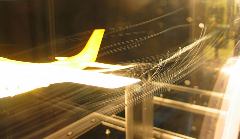
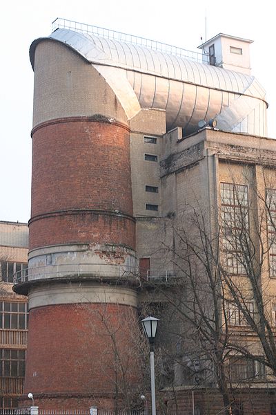
The Wright brothers' use of a simple wind tunnel in 1901 to study the effects of airflow over various shapes while developing their Wright Flyer was in some ways revolutionary. It can be seen from the above, however, that they were simply using the accepted technology of the day, though this was not yet a common technology in America. Subsequent use of wind tunnels proliferated as the science of aerodynamics and discipline of aeronautical engineering were established and air travel and power were developed. Wind tunnels were often limited in the volume and speed of airflow which could be delivered. The wind tunnel used by German scientists at Peenemünde prior to and during WWII is an interesting example of the difficulties associated with extending the useful range of large wind tunnels. It used some large natural caves which were increased in size by excavation and then sealed to store large volumes of air which could then be routed through the wind tunnels. This innovative approach allowed lab research in high-speed regimes and greatly accelerated the rate of advance of Germany's aeronautical engineering efforts. Later research into airflows near or above the speed of sound used a related approach. Metal pressure chambers were used to store high-pressure air which was then accelerated through a nozzle designed to provide supersonic flow. The observation or instrumentation chamber ("test section") was then placed at the proper location in the throat or nozzle for the desired airspeed. For limited applications, Computational fluid dynamics (CFD) can augment or possibly replace the use of wind tunnels. For example, the experimental rocket plane SpaceShipOne was designed without any use of wind tunnels. However, on one test, flight threads were attached to the surface of the wings, performing a wind tunnel type of test during an actual flight in order to refine the computational model. It should be noted that, for situations where external turbulent flow is present, CFD is not practical due to limitations in present day computing resources. For example, an area that is still much too complex for the use of CFD is determining the effects of flow on and around structures, bridges, terrain, etc.
The most effective way to simulative external turbulent flow is through the use of a boundary layer wind tunnel. There are many applications for boundary layer wind tunnel modeling. For example, understanding the impact of wind on high-rise buildings, factories, bridges, etc. can help building designers construct a structure that stands up to wind effects in the most efficient manner possible. Another significant application for boundary layer wind tunnel modeling is for understanding exhaust gas dispersion patterns for hospitals, laboratories, and other emitting sources. Other examples of boundary layer wind tunnel applications are assessments of pedestrian comfort and snow drifting. Wind tunnel modeling is accepted as a method for aiding in Green building design. For instance, the use of boundary layer wind tunnel modeling can be used as a credit for Leadership in Energy and Environmental Design (LEED) certification through the U.S. Green Building Council.
Wind tunnel tests in a boundary layer wind tunnel allow for the natural drag of the earth's surface to be simulated. For accuracy, it is important to simulate the mean wind speed profile and turbulence effects within the atmospheric boundary layer. Most codes and standards recognize that wind tunnel testing can produce reliable information for designers, especially when their projects are in complex terrain or on exposed sites. How it works
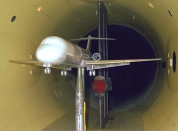
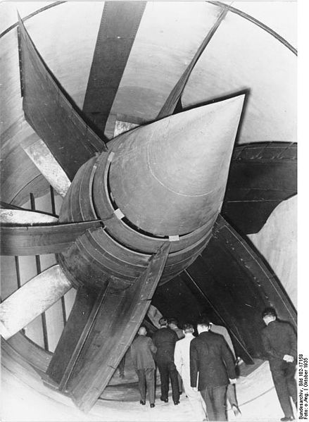
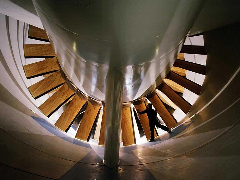
Air is blown or sucked through a duct equipped with a viewing port and instrumentation where models or geometrical shapes are mounted for study. Typically the air is moved through the tunnel using a series of fans. For very large wind tunnels several meters in diameter, a single large fan is not practical, and so instead an array of multiple fans are used in parallel to provide sufficient airflow. Due to the sheer volume and speed of air movement required, the fans may be powered by stationary turbofan engines rather than electric motors. The airflow created by the fans that is entering the tunnel is itself highly turbulent due to the fan blade motion (when the fan is blowing air into the test section - when it is sucking air out of the test section downstream, the fan-blade turbulence is not a factor), and so is not directly useful for accurate measurements. The air moving through the tunnel needs to be relatively turbulence-free and laminar. To correct this problem, closely-spaced vertical and horizontal air vanes are used to smooth out the turbulent airflow before reaching the subject of the testing. Due to the effects of viscosity, the cross-section of a wind tunnel is typically circular rather than square, because there will be greater flow constriction in the corners of a square tunnel that can make the flow turbulent. A circular tunnel provides a smoother flow. The inside facing of the tunnel is typically as smooth as possible, to reduce surface drag and turbulence that could impact the accuracy of the testing. Even smooth walls induce some drag into the airflow, and so the object being tested is usually kept near the center of the tunnel, with an empty buffer zone between the object and the tunnel walls. There are correction factors to relate wind tunnel test results to open-air results. Lighting is usually recessed into the circular walls of the tunnel and shines in through windows. If the light were mounted on the inside surface of the tunnel in a conventional manner, the light bulb would generate turbulence as the air blows around it. Similarly, observation is usually done through transparent portholes into the tunnel. Rather than simply being flat discs, these lighting and observation windows may be curved to match the cross-section of the tunnel and further reduce turbulence around the window. Various techniques are used to study the actual airflow around the geometry and compare it with theoretical results, which must also take into account the Reynolds number and Mach number for the regime of operation. Pressure measurementsPressure across the surfaces of the model can be measured if the model includes pressure taps. This can be useful for pressure-dominated phenomena, but this only accounts for normal forces on the body. Force and moment measurements
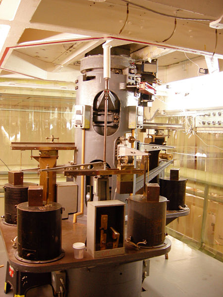
With the model mounted on a force balance, one can measure lift, drag, lateral forces, yaw, roll, and pitching moments over a range of angle of attack. This allows one to produce common curves such as lift coefficient versus angle of attack (shown). Note that the force balance itself creates drag and potential turbulence that will affect the model and introduce errors into the measurements. The supporting structures are therefore typically smoothly shaped to minimize turbulence. Flow visualizationBecause air is transparent it is difficult to directly observe the air movement itself. Instead, a smoke particulate or a fine mist of liquid is sprayed into the tunnel just ahead of the device being tested. The particulate is sufficiently low mass to stay suspended in the air without falling to the floor of the tunnel, and is light enough to easily move with the airflow. If the air movement in the tunnel is sufficiently non-turbulent, a particle stream released into the airflow will not break up as the air moves along, but stays together as a sharp thin line. Multiple particle streams released from a grid of many nozzles can provide a dynamic three-dimensional shape of the airflow around the object being tested. As with the force balance, these injection pipes and nozzles need to be shaped in a manner that minimizes the introduction of turbulent airflow into the airstream. High-speed turbulence and vortices can be difficult to see directly, but strobe lights and film cameras or high-speed digital cameras can help to capture events that are a blur to the naked eye. High-speed cameras are also required when the subject of the test is itself moving at high speed, such as an airplane propeller. The camera can capture stop-motion images of how the blade cuts through the particulate streams and how vortices are generated along the trailing edges of the moving blade. Wind tunnel classificationThere are many different kinds of wind tunnels, an overview is given in the figure below: List of wind tunnels
Aquadynamic FlumeThe aerodynamic principles of the wind tunnel work equally on watercraft, except the water is more viscous and so imposes a greater forces on the object being tested. A looping flume is typically used for underwater aquadynamic testing. The interaction between 2 different types of fluids means that pure windtunnel testing is only partly relevant. However, a similar sort of research is done in a towing tank Low-speed Oversize Liquid TestingAir is not always the best test medium to study small-scale aerodynamic principles, due to the speed of the air flow and airfoil movement. A study of fruit fly wings designed to understand how the wings produce lift was performed using a large tank of mineral oil and wings 100 times larger than actual size, in order to slow down the wing beats and make the vortices generated by the insect wings easier to see and understand. Wind Tunnel Testing for Structural DesignWind Tunnel Tests are carried out for measuring the pressures at certain points of structures. Usually very tall buildings, buildings with unusual or complicated shapes (such as a tall building with a parabolic or a hyperbolic shape), cable suspension bridges or cable stayed bridges are analysed in wind tunnels. Wind tunnel tests provide the necessary design pressure measurements for use in the dynamic analysis of the structure. See also
External links
Text from Wikipedia is available under the Creative Commons Attribution/Share-Alike License; additional terms may apply.
Published in July 2009. Click here to read more articles related to aviation and space!
|

 |
|
Copyright 2004-2026 © by Airports-Worldwide.com, Vyshenskoho st. 36, Lviv 79010, Ukraine Legal Disclaimer |