 |
 |
|
||||
|
By
Wikipedia,
VOR, short for VHF Omni-directional Radio Range, is a type of radio navigation system for aircraft. A VOR ground station broadcasts a VHF radio composite signal including the station's identifier in morse code (and sometimes a voice identifier), and data that allows the airborne receiving equipment to derive a magnetic bearing from the station to the aircraft (direction from the VOR station in relation to the Earth's magnetic North at the time of installation). VOR stations in areas of magnetic compass unreliability are oriented with respect to True North. This line of position is called the "radial" from the VOR. The intersection of two radials from different VOR stations on a chart allows for a "fix" or approximate position of the aircraft. Developed from earlier Visual-Aural Range (VAR) systems, the VOR was designed to provide 360 courses to and from the station selectable by the pilot. Early vacuum tube transmitters with mechanically-rotated antennas were widely installed in the 1950s, and began to be replaced with fully solid-state units in the early 1960s. They became the major radio navigation system in the 1960s, when they took over from the older radio beacon and four-course (low/medium frequency range) system. Some of the older range stations survived, with the four-course directional features removed, as non-directional low or medium frequency radiobeacons (NDBs). The VOR's major advantage is that the radio signal provides a reliable line (radial) from the station which can be selected and followed by the pilot. A worldwide land-based network of "air highways", known in the US as Victor airways (below 18,000 feet) and "jet routes" (at and above 18,000 feet), was set up linking VORs. An aircraft could follow a specific path from station to station by tuning the successive stations on the VOR receiver, and then either following the desired course on a Radio Magnetic Indicator, or setting it on a Course Deviation Indicator (CDI, shown below) or a Horizontal Situation Indicator (HSI, a more sophisticated version of the VOR indicator) and keeping a course pointer centered on the display.
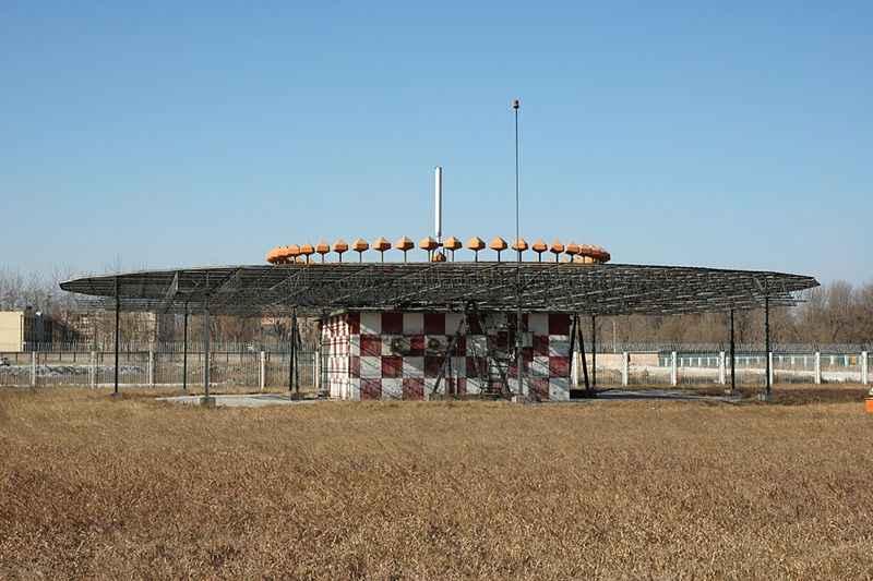
VORs provide considerably greater accuracy and reliability than NDBs due to a combination of factors in their construction -- specifically, less course bending around terrain features and coastlines, and less interference from thunderstorms. Although VOR transmitters were more expensive to install and maintain, today VOR has almost entirely replaced the low/medium frequency ranges and beacons in civilian aviation, and is now in the process of itself being supplanted by the Global Positioning System (GPS). Because they work in the VHF band, VOR stations rely on "line of sight" -- if the transmitting antenna could not be seen on a perfectly clear day from the receiving antenna, a useful signal cannot be received. This limits VOR (and DME) range to the horizon -- or closer if mountains intervene. This means that an extensive network of stations is needed to provide reasonable coverage along main air routes. The VOR network is a significant cost in operating the current airway system, although the modern solid state transmitting equipment requires much less maintenance than the older units. How VORs workVORs are assigned radio channels between 108.0 MHz (megahertz) and 117.95 MHz (with 50 kHz spacing); this is in the VHF (very high frequency) range. The VOR uses the phase relationship between a reference-phase and a rotating-phase signal to encode direction. The carrier signal is omni-directional and contains an amplitude modulated (AM) station Morse code or voice identifier. The reference 30 Hz signal is frequency modulated (FM) on a 9960 Hz sub-carrier. A second, amplitude modulated (AM) 30 Hz signal is derived from the rotation of a directional antenna array 30 times per second. Although older antennas were mechanically rotated, current installations scan electronically to achieve an equivalent result with no moving parts. When the signal is received in the aircraft, the two 30 Hz signals are detected and then compared to determine the phase angle between them. The phase angle is equal to the direction from the station to the aircraft, in degrees from local magnetic north, and is called the "radial." This information is then fed to one of three common types of indicators:
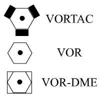
In many cases the VOR stations have co-located DME (Distance Measuring Equipment) or military TACAN (TACtical Air Navigation -- the latter includes both the distance feature, DME, and a separate TACAN azimuth feature that provides military pilots data similar to the civilian VOR). A co-located VOR and TACAN beacon is called a VORTAC. A VOR with co-located DME only is called a VOR-DME. A VOR radial with DME distance allows a one-station position fix. Both VOR-DMEs and TACANs share the same DME system. VORTACs and VOR-DMEs use a standardized scheme of VOR frequency - TACAN channel pairing so that a specific VOR frequency is always paired with a specific channel for the co-located TACAN or DME feature; on civilian equipment, the VHF frequency is tuned and the appropriate TACAN channel is automatically selected. Some VORs have a relatively small geographic area protected from interference by other stations on the same frequency -- called "terminal" or T-VORs. Other stations may have protection out to 130 nautical miles (NM) or more. Although it is popularly thought that there is a standard difference in power output between T-VORs and other stations, in fact the stations' power output is set to provide adequate signal strength in the specific site's service volume. Using a VORIf a pilot wants to approach the VOR station from due east then the aircraft will have to fly due west to reach the station. The pilot will use the OBS to rotate the compass dial until the number 27 (270 degrees) aligns with the pointer (called the Primary Index) at the top of the dial. When the aircraft intercepts the 90-degree radial (due east of the VOR station) the needle will be centered and the To/From indicator will show "To". Notice that the pilot set the VOR to indicate the reciprocal; the aircraft will follow the 90-degree radial while the VOR indicates that the course "to" the VOR station is 270 degrees. This is called "proceeding inbound on the 090 radial." The pilot needs only to keep the needle centered to follow the course to the VOR station. If the needle drifts off-center the aircraft would be turned towards the needle until it is centered again. After the aircraft passes over the VOR station the To/From indicator will indicate "From" and the aircraft is then proceeding outbound on the 270 degree radial. The CDI needle may oscillate or go to full scale in the "cone of confusion" directly over the station but will recenter once the aircraft has flown a short distance beyond the station. In the illustration on the right, notice that the heading ring is set with 254 degrees at the primary index, the needle is centered and the To/From indicator is showing "From" (FR). The VOR is indicating that the aircraft is on the 254 degree radial, west-southwest "from" the VOR station. If the To/From indicator were showing "To" it would mean the aircraft was on the 74-degree radial and the course "to" the VOR station was 254 degrees. Note that there is absolutely no indication of what direction the aircraft is flying. The aircraft could be flying due north and this snapshot of the VOR could be the moment when it crossed the 254 degree radial. Positive Sensing and Reverse SensingThe term positive sensing is used when the pilot turns in the direction of needle deflection and the needle centers up. On the opposite side, the term reverse sensing is when the pilot turns in the direction of the needle and the needle deflects farther away from the center. Many student pilots are convinced that positive sensing occurs when the aircraft is traveling towards the VOR station and once passed becomes reverse sensing. This is not the case and positive sensing is quite easy to identify as well as reverse sensing. Thus positive sensing can be identified by this equation. If the current heading of the airplane is found on the top half of the VOR indicator, the pilot is assured of positive sensing. If the current heading is on the bottom half of the VOR indicator, reverse sensing is in order. Using a standard method to intercept a VOR radial will decrease the chances of a pilot flying with reverse sensing. This phenomenon has nothing to do with how a VOR indicator works but how the human mind interprets the indications. Intercepting VOR RadialsThere are many methods available to determine what heading to fly to intercept a radial from the station or a course to the station. The most common method involves the acronymn T-I-T-P-I-T. The acronym stands for Tune - Identify - Twist - Parallel - Intercept - Track. Each of these steps are quite important to ensure the airplane is headed where it is being directed. First, tune the desired VOR frequency into the navigation radio, second and most important, Identify the correct VOR station by verifying the morse code heard with the sectional chart. Third, twist the VOR OBS knob to the desired radial (FROM) or course (TO) the station. Fourth, bank the airplane till the heading indicator indicates the radial or course set in the VOR. The fifth step is to fly towards the needle. If the needle is to the left, turn left by 30-45 degrees and vice versa. The last step is once the VOR needle is centered, turn the heading of the airplane back to the radial or course to track down the radial or course flown. If there is wind, a wind correction angle will be necessary to maintain the VOR needle centered. Another method to intercept a VOR radial exists and more closely aligns itself with the operation of an HSI (Horizontal Situation Indicator). The first three steps above are the same; tune, identify and twist. At this point, the VOR needle should be displaced to either the left or the right. Looking at the VOR indicator, the numbers on the same side as the needle will always be the headings needed to return the needle back to center. The aircraft heading should then be turned to align itself with one of those shaded headings. If done properly, this method will never produce reverse sensing. A good example is this, an airplane is traveling in the northwest quadrant in relation to the VOR. The exact VOR radial the aircraft is on is 315 degrees. After tuning, identifying and twisting the OBS knob to 360 degrees, the needle deflects to the right. The needle shades the numbers between 360 and 090. If the airplane turns to a heading anywhere in this range, the airplane will intercept the radial. How is reverse sensing negated using this method? In the previous exercise, if the airplane was flying a heading of 180 degrees, the needle will still deflect right showing the correct headings to fly but from the pilot's perspective it will seem to indicate a turn westerly. The pilot should turn left even though the needle points right, as it is a shorter turn to a heading of 045 degrees to intercept the radial. Using this method will ensure quick understanding of how an HSI works as the HSI visually shows what we are mentally trying to do. Try out Luiz Monteiro's websiteon VOR's to comfirm this method. VORs, Airways and the Enroute Structure
VOR and the older NDB stations were traditionally used as intersections along airways. A typical airway will hop from station to station in straight lines. As you fly in a commercial airliner you will notice that the aircraft flies in straight lines occasionally broken by a turn to a new course. These turns are often made as the aircraft passes over a VOR station. Navigational reference points can also be defined by the point at which two radials from different VOR stations intersect, or by a VOR radial and a DME distance. This is the basic form of RNAV and allows navigation to points located away from VOR stations. As RNAV systems have become more common, in particular those based upon GPS, more and more airways have been defined by such points, removing the need for some of the expensive ground-based VORs. A recent development is that, in some airspace, the need for such points to be defined with reference to VOR ground stations has been removed. This has led to predictions that VORs will be obsolete within a decade or so. There are three types of VORs: High Altitude, Low Altitide and Terminal. The range of the three differ. Terminal VORs are accurate to 25NMs outward up to 12,000ft. In many countries there are two separate systems of airway at lower and higher levels: the lower Airways (known in the US as Victor Airways) and Upper Air Routes (known in the US as Jet routes). Most aircraft equipped for instrument flight (IFR) have at least two VOR receivers. As well as providing a backup to the primary receiver, the second receiver allows the pilot to easily follow a radial toward one VOR station while watching the second receiver to see when a certain radial from another VOR station is crossed. AccuracyThe predictable accuracy of the VOR system is ±1.4°. However, test data indicate that 99.94% of the time a VOR system has less than ±0.35° of error. Internal monitoring of a VOR station will shut it down if the station error exceeds 1.0°. ARINC 711-10 January 30, 2002 states that receiver accuracy should be within 0.4 degrees with a statistical probability of 95% under various conditions. Any receiver compliant to this standard should meet or exceed these tolerances. Radio-navigation aids must keep a certain degree of accuracy (given by international standards, FAA, ICAO...); to assure this is the case, Flight inspection organizations check periodically critical parameters with properly equipped aircraft to calibrate and certify VOR precision. Future
Like many other forms of aircraft radio navigation currently used, it is likely that some form of space-based navigational system such as Global Positioning System (GPS) will replace VOR systems. VOR is specifically in jeopardy because of the need for numerous stations to cover a large area. The satellite-based GPS is capable of reliably locating an aircraft's position within about 100 feet horizontally. Augmented by "Wide Area Augmentation System" (WAAS) currently being deployed in the U.S., the error is reduced to a cube about 10 feet on each side. This allows precision instrument approaches (with lateral and vertical guidance) with landing weather minima nearly as low as the Category I Instrument Landing System -- but with no ground-based equipment except for a relatively few units that determine the WAAS correction signals relayed through satellites to user aircraft. Further refinements include "Local Area Augmentation System" (LAAS) which will probably allow Category III approaches (practically speaking, landings in "zero-zero" weather) -- again, with minimal requirement for ground stations. LAAS is planned to use the same VHF band for its correction message. This might require some existing VOR facilities to be shut down or shifted to different frequencies to avoid interference issues. As of 2008 in the USA GPS-based approaches outnumber VOR-based approaches. More and more, conventional VOR navigation equipment is being phased out or replaced by integrated avionics packages that also contain one or more VOR receivers. Old VOR navigation equipment is put to new use in experimental aircraft projects, as is shown exemplary by this Ibis canard aircraft instrument panel development report. See also
External links
Text from Wikipedia is available under the Creative Commons Attribution/Share-Alike License; additional terms may apply.
Published in July 2009. Click here to read more articles related to aviation and space!
|

 |
|
Copyright 2004-2026 © by Airports-Worldwide.com, Vyshenskoho st. 36, Lviv 79010, Ukraine Legal Disclaimer |