 |
 |
|
||||
|
By
Wikipedia,
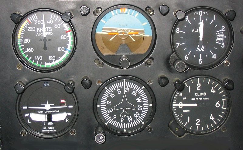
Flight instrumentsMost aircraft have these flight instruments: AltimeterThe altimeter shows the aircraft's height (usually in feet or meters) above some reference level (usually sea-level) by measuring the local air pressure. It is adjustable for local barometric pressure (referenced to sea level) which must be set correctly to obtain accurate altitude readings. Attitude indicatorThe attitude indicator (also known as an artificial horizon) shows the aircraft's attitude relative to the horizon. From this the pilot can tell whether the wings are level and if the aircraft nose is pointing above or below the horizon. This is a primary instrument for instrument flight and is also useful in conditions of poor visibility. Pilots are trained to use other instruments in combination should this instrument or its power fail.
Airspeed indicatorThe airspeed indicator shows the aircraft's speed (usually in knots) relative to the surrounding air. It works by measuring the ram-air pressure in the aircraft's pitot tube. The indicated airspeed must be corrected for air density (which varies with altitude, temperature and humidity) in order to obtain the true airspeed, and for wind conditions in order to obtain the speed over the ground. Magnetic compassThe compass shows the aircraft's heading relative to magnetic north. While reliable in steady level flight it can give confusing indications when turning, climbing, descending, or accelerating due to the inclination of the earth's magnetic field. For this reason, the heading indicator is also used for aircraft operation. For purposes of navigation it may be necessary to correct the direction indicated (which points to a magnetic pole) in order to obtain direction of true north or south (which points to the earth's axis of rotation). Heading indicatorThe heading indicator (also known as the directional gyro, or DG; sometimes also called the gyrocompass, though usually not in aviation applications) displays the aircraft's heading with respect to geographical north. Principle of operation is a spinning gyroscope, and is therefore subject to drift errors (called precession) which must be periodically corrected by calibrating the instrument to the magnetic compass. In many advanced aircraft (including almost all jet aircraft), the heading indicator is replaced by a Horizontal Situation Indicator (HSI) which provides the same heading information, but also assists with navigation. Turn and bank indicatorThe turn and bank indicator (or turn coordinator or turn indicator) displays direction of turn and rate of turn. Internally mounted inclinometer displays 'quality' of turn, i.e. whether the turn is correctly coordinated, as opposed to an uncoordinated turn, wherein the aircraft would be in either a slip or a skid. Replaced in the late sixties and early seventies by the newer turn coordinator, the turn and bank is typically only seen in aircraft manufactured prior to that time, or in gliders manufactured in Europe.
Vertical speed indicatorThe vertical speed indicator (also sometimes called a variometer). Senses changing air pressure, and displays that information to the pilot as a rate of climb or descent in feet per minute, meters per second or knots. Layout
Most aircraft are equipped with a standard set of flight instruments which give the pilot information about the aircraft's attitude, airspeed, and altitude. T arrangementMost aircraft built since about 1953 have four of the flight instruments located in a standardized pattern called the T arrangement. The attitude indicator is in the top center, airspeed to the left, altitude to the right and heading indicator under the attitude indicator. The other two, turn-coordinator and vertical-speed, are usually found under the airspeed and altitude, but are given more latitude in placement. The magnetic compass will be above the instrument panel, often on the windscreen centerpost. In newer aircraft with glass cockpit instruments the layout of the displays conform to the basic T arrangement. Basic SixIn 1937 the Royal Air Force (RAF) chose a set of six essential flight instruments which would remain the standard panel used for flying in Instrument Meteorological Conditions (IMC) for the next 20 years. They were:
This panel arrangement was incorporated into every RAF aircraft, from the light Tiger Moth, to the heavy, such as the Avro Lancaster, and minimised the type-conversion difficulties associated with Blind Flying, a pilot trained on a Tiger Moth could quickly become accustomed to any other aircraft, the blind flying instruments being identical. This Basic Six set was also adopted by commercial aviation. After the Second World War the arrangement was changed to: (top row) airspeed, artificial horizon, altimeter, (bottom row) radio compass, direction indicator, vertical speed. See alsoExternal links
Text from Wikipedia is available under the Creative Commons Attribution/Share-Alike License; additional terms may apply.
Published in July 2009. Click here to read more articles related to aviation and space!
|

 |
|
Copyright 2004-2024 © by Airports-Worldwide.com, Vyshenskoho st. 36, Lviv 79010, Ukraine Legal Disclaimer |